Hi Mike,
Understood.
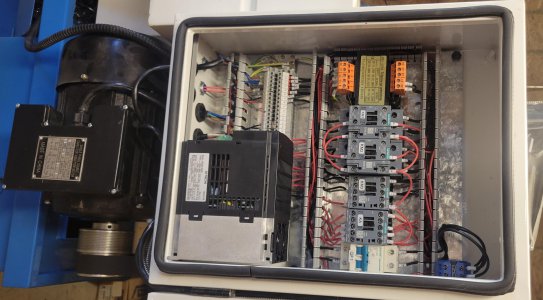
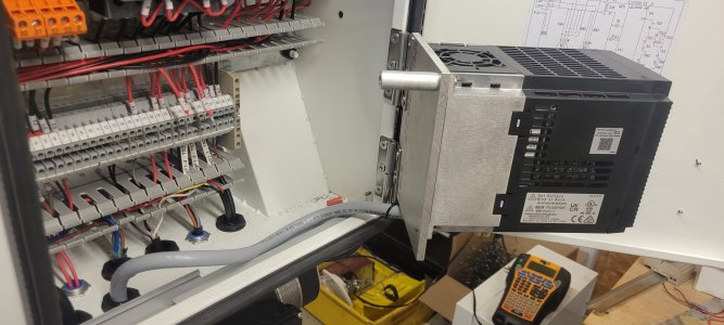
I had a similar problem with insufficient DIN rail space. I added a short section next to the VFD. You can see it in the photos. What I was trying to say is that perhaps you want to put a volt meter in the same housing as the RPM meter is in. You will have already run the 12V there, but you will need a wire to your pot, where ever that is located and you will need to be aware of the ground lines making unnecessary runs or loops to avoid noise. By the way the digital displays do make some switching noise as the segments change. The more active segments the more current the display requires. If your 12 volt supply is some distance from the displays you may want to add some capacitance at the power connections at the displays. I did not have to add capacitance, but the need for controlling noise is dependent upon the arrangement of things.
Anyway, I like having the ability to see what frequency the VFD is going to be running at before turning on the motor.
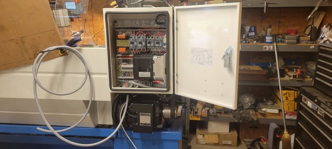
I am looking forward to seeing your final circuit and physical layout. So do post them.
Dave
PS. Unless you are just into building and modifying the lathe and its features, once you get the lathe up, it is working ok and you are making things you probably will never go back and make changes. You know the old saying "If it isn't broken don't fix it." That is probably why, even though I have designed and built a pcb to replace my hand wired board, I have yet to replace it. Also, as I have found not all lathe's have the same space for the switches, knobs, display etc control features in the front panel, so, for example, perhaps the pcb connectors should be laid out differently or some features are more desirable than others.
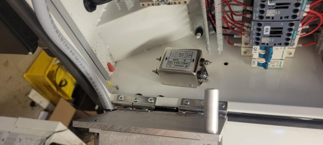
Oh, one other thing you mentioned. About hinging things. There are a lot of wires going to the VFD and some of them are pretty stiff. Likewise, the motor and power wires are very stiff. I would think that hinging such that wires have to move would NOT be good. Things come loose or break and it is not always obvious and they may short out. You also mentioned turning the VFD. I did this and it works fine.
I also wanted the air that is being blown through the VFD heat sink to exit in the opposite direction (to cause flow in the enclosure across my electronic-brake resistor) and the little fan that is built into the VFD does flip right around just fine. Turns out the electronic brake never gets hot anyway. There is only power being dissapated in the resistor when the VFD is braking the motor. It might get warm if you were rapidly starting and stopping the motor and that never happens on our lathes. At least I am not familar with any application where this is happening. People do not seem to understand that this braking resistor only gets warm if the load is hugh and the VFD is being use to control dynamic speed changes. Things like this happen in paper mills etc. where large rolls of paper are being speed controlled to transport webs without breaking them. I have not seen any lathes the size of ours that would even ever be run like this. Hence, the 300 and 400 watt resistors are way over kill.
Understood.
I had a similar problem with insufficient DIN rail space. I added a short section next to the VFD. You can see it in the photos. What I was trying to say is that perhaps you want to put a volt meter in the same housing as the RPM meter is in. You will have already run the 12V there, but you will need a wire to your pot, where ever that is located and you will need to be aware of the ground lines making unnecessary runs or loops to avoid noise. By the way the digital displays do make some switching noise as the segments change. The more active segments the more current the display requires. If your 12 volt supply is some distance from the displays you may want to add some capacitance at the power connections at the displays. I did not have to add capacitance, but the need for controlling noise is dependent upon the arrangement of things.
Anyway, I like having the ability to see what frequency the VFD is going to be running at before turning on the motor.
I am looking forward to seeing your final circuit and physical layout. So do post them.
Dave
PS. Unless you are just into building and modifying the lathe and its features, once you get the lathe up, it is working ok and you are making things you probably will never go back and make changes. You know the old saying "If it isn't broken don't fix it." That is probably why, even though I have designed and built a pcb to replace my hand wired board, I have yet to replace it. Also, as I have found not all lathe's have the same space for the switches, knobs, display etc control features in the front panel, so, for example, perhaps the pcb connectors should be laid out differently or some features are more desirable than others.
Oh, one other thing you mentioned. About hinging things. There are a lot of wires going to the VFD and some of them are pretty stiff. Likewise, the motor and power wires are very stiff. I would think that hinging such that wires have to move would NOT be good. Things come loose or break and it is not always obvious and they may short out. You also mentioned turning the VFD. I did this and it works fine.
I also wanted the air that is being blown through the VFD heat sink to exit in the opposite direction (to cause flow in the enclosure across my electronic-brake resistor) and the little fan that is built into the VFD does flip right around just fine. Turns out the electronic brake never gets hot anyway. There is only power being dissapated in the resistor when the VFD is braking the motor. It might get warm if you were rapidly starting and stopping the motor and that never happens on our lathes. At least I am not familar with any application where this is happening. People do not seem to understand that this braking resistor only gets warm if the load is hugh and the VFD is being use to control dynamic speed changes. Things like this happen in paper mills etc. where large rolls of paper are being speed controlled to transport webs without breaking them. I have not seen any lathes the size of ours that would even ever be run like this. Hence, the 300 and 400 watt resistors are way over kill.
Last edited: