School me on CAD, CAM, etc..

I would suggest viewing YT videos called "FreeCAD for Beginners" by Adventures in Creation. He as a series from #1 to #27 (so far). Very good and detailed while not getting bogged down.
When I started learning FreeCAD, I followed @devils4ever 's advice. Don't be afraid to replay the videos, even at slower than real time, to watch the mouse movements, clicks and things. If you get hung up on anything, start a thread in the FreeCAD sub-forum. It is under the CAD forum.

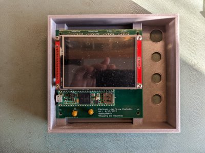
Here's the box I printed last night as a draft, to check for fit. There's room for improvement, but not terrible for my first print from my own design. Connectors fit, the holes line up, the overall height is correct, so it's onto adding the connector cutout for the USB cable, extending the bosses to the top for the lid, and relocating the GX connectors, to give a little more room for the nut, and designing a lid. I mistakenly designed the location of the connectors thinking the nut was on the outside. Whoops. Overall size 133 x 120 x 30 mm. The PCB was designed using KiCAD, an open source PCB design tool.

Unlike this printed box, the PCB worked the first time. Of course, I spent a week on the PCB design, and had bread boarded and tested the design, so I was pretty sure it would work. The hardest part was waiting for the PCB's. Took a month to get them, as I didn't want or need to pay a premium. Lucked out on some introductory pricing, five boards cost me $2 total. That's including shipping from 1/2 way around the world.
PXL_20221117_132746393.jpg
 
When I started learning FreeCAD, I followed @devils4ever 's advice. Don't be afraid to replay the videos, even at slower than real time, to watch the mouse movements, clicks and things. If you get hung up on anything, start a thread in the FreeCAD sub-forum. It is under the CAD forum.

Here's the box I printed last night as a draft, to check for fit. There's room for improvement, but not terrible for my first print from my own design. Connectors fit, the holes line up, the overall height is correct, so it's onto adding the connector cutout for the USB cable, extending the bosses to the top for the lid, and relocating the GX connectors, to give a little more room for the nut, and designing a lid. I mistakenly designed the location of the connectors thinking the nut was on the outside. Whoops. Overall size 133 x 120 x 30 mm. The PCB was designed using KiCAD, an open source PCB design tool.

Unlike this printed box, the PCB worked the first time. Of course, I spent a week on the PCB design, and had bread boarded and tested the design, so I was pretty sure it would work. The hardest part was waiting for the PCB's. Took a month to get them, as I didn't want or need to pay a premium. Lucked out on some introductory pricing, five boards cost me $2 total. That's including shipping from 1/2 way around the world.
Curious what you use for CAM? I retired at the end of February this year and have learning CAD/CAM on my "list of good intentions". My wife is a UG designer, but she runs around our house like the Energizer Bunny on her own projects. I'm trying to avoid drawing her into my projects, but in a pinch, "Honey, can you look at this?"

I run a Tormach 1100; it'd be great to have a CAD package to do the drawing, CAM to generate the G-codes and a post-processor to do the refinements for the unique features of my machine. The guy I bought my Tormach from was a Fusion user; I figured I'd dip my toe into something free before deciding on a paid upgrade.

Thanks! Bruce
 
I went the route to FreeCAD, with a whole lot of help and discussion from this forum.
The whole debate, and comparisons to Fusion360 was explored.
Here --> FreeCAD - Gorgeous! I am a little intimidated!
Now, I run FreeCAD 2.0.

The absolute key to getting into it is to use the excellent videos on YouTube. Do not try to get every tool on the desktop explored on day 1. FreeCAD is incredibly flexible in style and feel, so if you want to use mouse gestures or colours, whatever from other platforms, they are there, but start with the defaults.

I switched the display line thickness for edges to 1 pixel, and I went for a flat plain colour instead of gradient shaded, but that was about it.
In fairness, the learning curve happens easier when one is in lockdown isolation :)

AVOID the videos that do not offer audio narration and explanation. Watching a sequence of mouse moves to music massively blunts the learning experience! You can, of course, pause, or run at slower speed if you are following an example on your own open window. I use two screens, one for the browser on YouTube, and the other for the FreeCAD software. I suppose one could use a phone, or a spare laptop, but my second screen was donated to me, and I find it very useful.

Here is starter example from JOKO (one of the best content creators) -->

.. and a look at producing drawings that you can get grubby in the shop -->

Exporting G-code and suchlike for 3D printers is there too, but we leave that for now. There are all sorts of tools (called workbenches), which I also leave for now. Some are for architecture, or finite element stress analysis. Just have a little explore. :)
you convinced me to try it at least... for when autodesk makes another bone head move
 
Curious what you use for CAM? I retired at the end of February this year and have learning CAD/CAM on my "list of good intentions". My wife is a UG designer, but she runs around our house like the Energizer Bunny on her own projects. I'm trying to avoid drawing her into my projects, but in a pinch, "Honey, can you look at this?"

I run a Tormach 1100; it'd be great to have a CAD package to do the drawing, CAM to generate the G-codes and a post-processor to do the refinements for the unique features of my machine. The guy I bought my Tormach from was a Fusion user; I figured I'd dip my toe into something free before deciding on a paid upgrade.

Thanks! Bruce
I'm far from a sophisticated user... I have only used this for making drawings and for 3d printing, not CAM.

All I have done to date is to use FreeCAD to generate an stl file, which is a simple export. It also supports export to 3mf and about 18+ other formats. I import the stl file into a slicer program, which generates the g-code.

I just checked the FreeCAD forums, and I see development on PATH/CAM, but I don't see any mainline plugins yet for CAM. There may be 3rd party stuff, but I haven't looked into it. Edit: There's https://github.com/aewallin/opencamlib OPENCAMLIB, but I know nothing about it.
 
+1 FreeCAD.

All CAD programs have a steep learning curve, but there are lots of YT videos and the forums for FreeCAD. It will be free forever which is why I chose it over F360 which I started with.

OK, I have to say it.

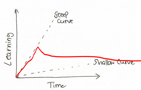
Ya'll, and I mean 99% of people are using the expression "steep learning curve" incorrectly. In fact if means just the opposite of what most people think. A steep learning curve characterizes a rapidly mastered task.

With CAD programs that would mean that you could be up and running in a day and design any part you wanted. That is not the case...

Below the steep curve illustrates that the task is mastered quickly. The red line I drew more closely resembles actual experience in CAD... you can learn the basics quickly but mastery takes long hard usage and learning continually and mastery always seems to allude you if you are not a regular user.

This is why I practice often and design every part I can think of

1668707257909.png
 
When I started learning FreeCAD, I followed @devils4ever 's advice. Don't be afraid to replay the videos, even at slower than real time, to watch the mouse movements, clicks and things. If you get hung up on anything, start a thread in the FreeCAD sub-forum. It is under the CAD forum.

Here's the box I printed last night as a draft, to check for fit. There's room for improvement, but not terrible for my first print from my own design. Connectors fit, the holes line up, the overall height is correct, so it's onto adding the connector cutout for the USB cable, extending the bosses to the top for the lid, and relocating the GX connectors, to give a little more room for the nut, and designing a lid. I mistakenly designed the location of the connectors thinking the nut was on the outside. Whoops. Overall size 133 x 120 x 30 mm. The PCB was designed using KiCAD, an open source PCB design tool.

Unlike this printed box, the PCB worked the first time. Of course, I spent a week on the PCB design, and had bread boarded and tested the design, so I was pretty sure it would work. The hardest part was waiting for the PCB's. Took a month to get them, as I didn't want or need to pay a premium. Lucked out on some introductory pricing, five boards cost me $2 total. That's including shipping from 1/2 way around the world.
View attachment 427037
what screen do you have in there?
 
what screen do you have in there?
ILI9341 touch panel. 320x240 pixels. 3.2" diagonal. Very good SW support, at least for a Teensy. More than adequate for a straight forward ELS control application. The size does make you frugal with your user interface. Not much room for eye candy, which is fine with me.
 
OK, I have to say it.

Ya'll, and I mean 99% of people are using the expression "steep learning curve" incorrectly. In fact if means just the opposite of what most people think. A steep learning curve characterizes a rapidly mastered task.

With CAD programs that would mean that you could be up and running in a day and design any part you wanted. That is not the case...

Below the steep curve illustrates that the task is mastered quickly. The red line I drew more closely resembles actual experience in CAD... you can learn the basics quickly but mastery takes long hard usage and learning continually and mastery always seems to allude you if you are not a regular user.

This is why I practice often and design every part I can think of

View attachment 427074
Ok. How about it's a steep climb! Steep climbs are harder and take longer, at least for the average Joe. Not talking about 5.11 climbers... Sometimes steep climbs intimidate people from even trying. With all CAD, there's a way to learn, it just takes time and motivation.
 
Ok. How about it's a steep climb! Steep climbs are harder and take longer, at least for the average Joe. Not talking about 5.11 climbers... Sometimes steep climbs intimidate people from even trying. With all CAD, there's a way to learn, it just takes time and motivation.
It's more akin to trekking the entire Appalachian trail than climbing Grays Peak, Colorado
 
ILI9341 touch panel. 320x240 pixels. 3.2" diagonal. Very good SW support, at least for a Teensy. More than adequate for a straight forward ELS control application. The size does make you frugal with your user interface. Not much room for eye candy, which is fine with me.
I want to use a touch screen on a project... and got vetoed by my collaborator for our tachometer project but we will use one on our own version of ELS/cnc add on control.
 
Back
Top