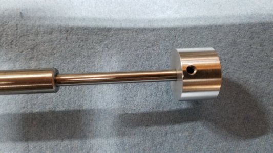
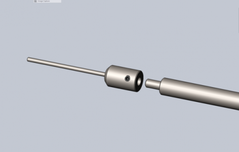
Spindle Stop

jbolt

Active User
H-M Supporter Gold Member
Joined
Dec 3, 2013
Messages
1,849
My version of a spindle stop for my PM-1440GT lathe with 2" spindle bore.

I have been using this stop for a while. Made from Delrin, a 3/* aluminum rod and 3/16" & 1/4" drill rod at the ends. It is held in place by one of the outboard spider setscrews and adjusted with a 1/4-20 setscrew. Something I made up quickly for a job. Works okay but a bit of a pain to quickly install and adjust.
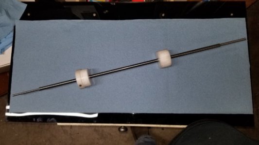
20180304_115433.jpg


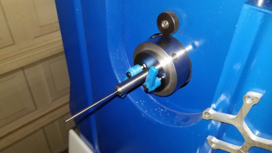
I decided to make one that was tool-less to install and adjust. The adapter is made from 2-1/4" 1018 cold rolled steel. The adapter is held in place by a pin that is engaged by a 1/4-20 adjustable handle. Same for the stop rod lock. The stop rod and lock pins are made from O-1 drill rod.

Cad Model showing how pins are engaged.
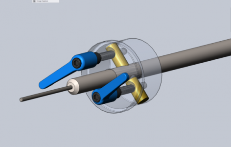
SindleStopAssm.png

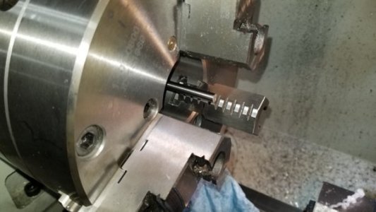
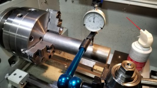
Truing up the stock in the 3-jaw prior to facing and drilling.
20180228_185919.jpg

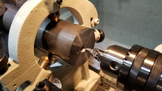
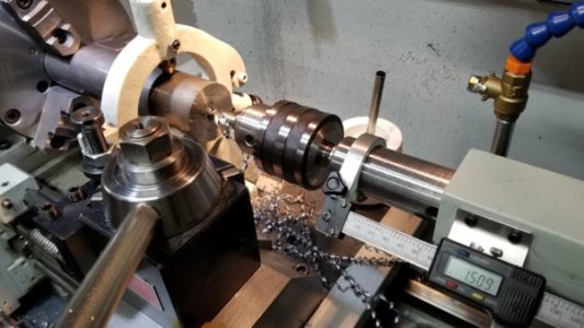
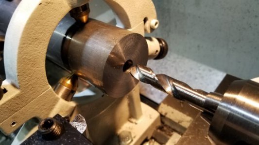
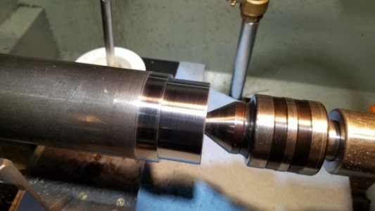
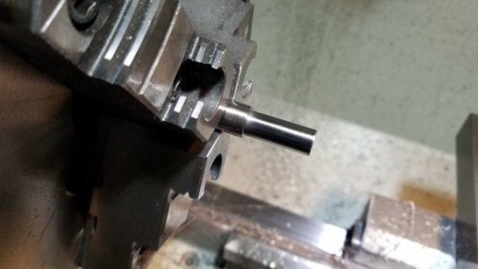
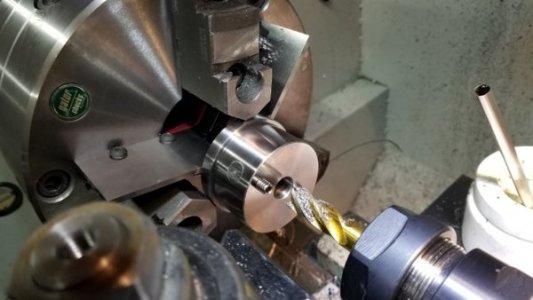
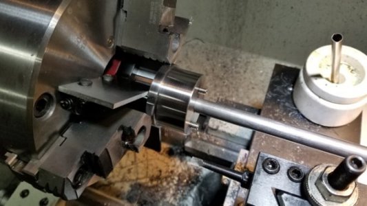
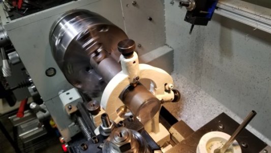
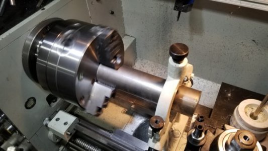
Stock supported in the steady for facing and drilling. I would have done the turning in the steady but I discovered it would not open more than 2" so I had to remove the collar the holds the top finger and lock the finger with a set screw. Okay for facing and drilling but sketchy for turning.
20180228_192819.jpg 20180228_192827.jpg 20180228_193411.jpg 20180228_193908.jpg 20180228_194519.jpg

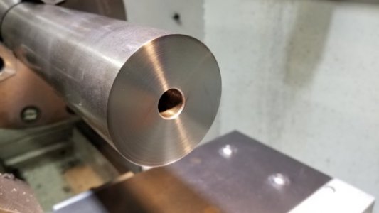
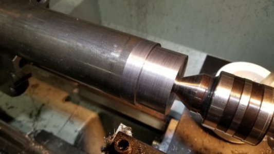
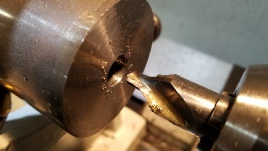
Used a larger center drill to make a flat for the live center.
20180228_194715.jpg

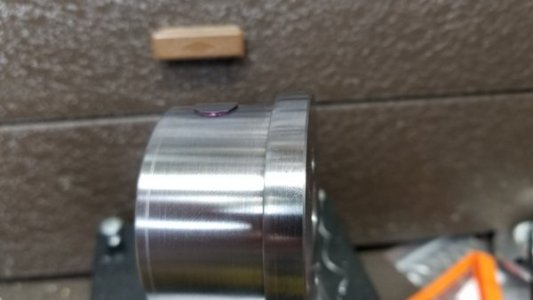
A quick hit with some 220 paper.

20180228_200207.jpg 20180228_200354.jpg 20180303_083950.jpg

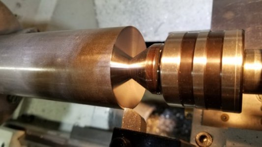
Chamfer tool. Everyone should have one!
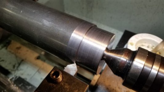
20180303_084111.jpg 20180303_085208.jpg

Stock was cut off in the horizontal band saw and then faced to size. Brass shim stock protects the turned and semi-polished area from being marred by the chuck jaws.
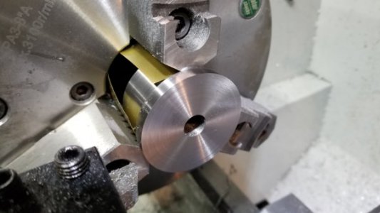
20180303_091845.jpg

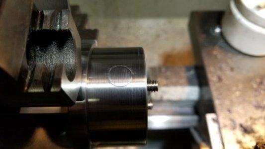
The adapter was turned 0.002" undersized for a slip fit into the outboard spider.
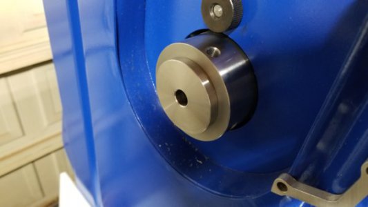
20180303_092725.jpg

To be continued.....
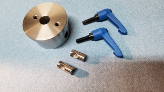
 
Moving on to the mill.

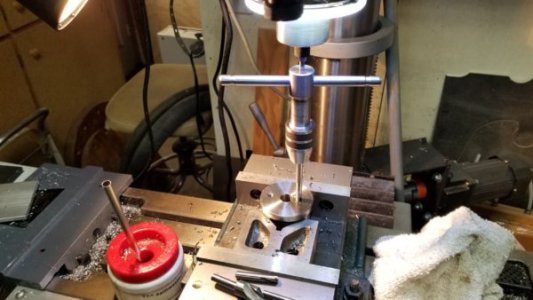
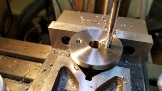
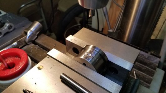
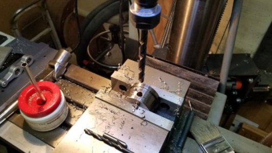
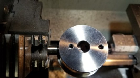
Holes for the adjustable handles are drilled and tapped.

20180303_113013.jpg20180303_113018.jpg

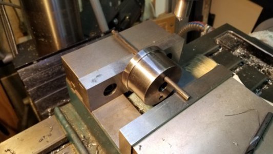
How to set up to drill perpendicular to the holes drilled through the face? Use gravity!

My mill is reasonably level so I hung the adapter from a rod to set the holes vertical.

20180303_114053.jpg20180303_114401.jpg
20180303_114613.jpg

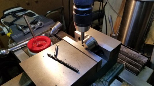
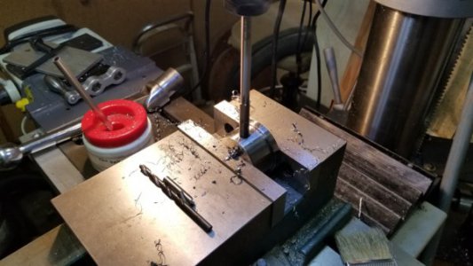
Spot drill.

20180303_114828.jpg

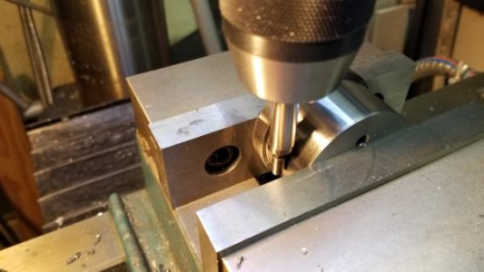
Drill undersized for reaming with a 3/8 reamer. Well that was the plan until I grabbed the .386 drill instead of the .368 drill. Fortunately I had a .3905 reamer otherwise they would have become .500 holes.

20180303_120430.jpg20180303_121311.jpg

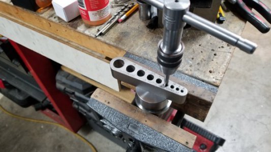
My 1/4-20 tap would not go all the way through so the back side of the holes were tapped separately. This side of the hole will be used to secure the locking pins during turning so the threads do not need to align with the front.

20180303_121839.jpg

Roughing out the locking pins from 1/2 drill rod.

20180303_140313.jpg

Checking the slip fit.

20180303_140331.jpg

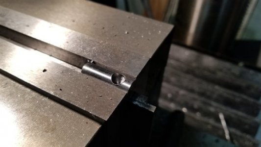
The side of the locking pin was first drilled to depth with a 90 degree point spotting drill and then finished with a 90 degree countersink. The pins were rough cut long and then marked for trimming once fitted.

20180303_142451.jpg

The pins were trimmed with just enough extra for turning. To set the pin a setscrew was installed in the front into the center drilled pocket until snug and then backed out one full turn then locked in place with a setscrew from the rear as seen below. The setscrews are the non-marring type. The face of the adapter lock pin was turned the the same inside diameter of the outboard spider to maximize the engagement surface area.

20180303_152051.jpg

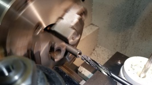
For the stop rod the lock pin was set and held in the same manner as the other pin. A 1/2" 4-flute center cutting end mill was used to remove the part of the pin that was protruding into the center hole. The hole was then bored 0.002 oversize with a boring bar.

20180303_153051.jpg

Test fit of the stop rod.

20180303_154530.jpg

This shows how much the pin moves when the setscrew is fully tightened.

20180303_154803.jpg

Ready for assembly.

20180303_160609.jpg

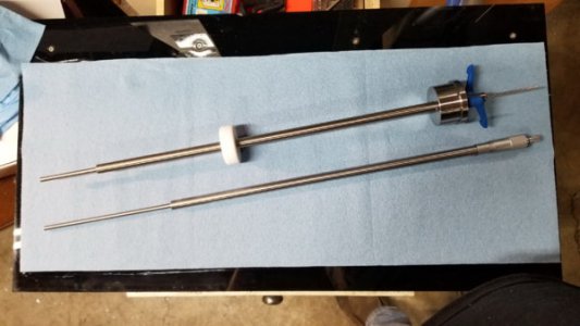
The stop rod shown in the adapter is made from 1/2 O-1 drill rod. One one end is a 15/64" drill rod and the other end is a 0.120 hardened M@ HHS tool steel rod blank. Both stick out 2-1/2". Each rod is held in place with Loctite 609 retention fluid. The white donut on the stop rod is made from white Delrin. This supports the stop rod inside the spindle and is secured with a set screw. The rod at the bottom is a micrometer stop rod which I will cover later.

20180304_113505.jpg

20180304_113734.jpg20180304_113743.jpg

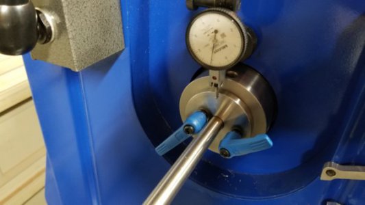
For use with a jawed chuck or an ER collet chuck there is no issue. I was concerned the locking system would not work with a 5C collet chuck since it pulls the stock in when tightening. I tested it with an indicator and was pleased to find that when the part was tightened for the first time I would get no more than 0.001 of movement of the spindle stop assembly and after the initial movement there wasn't anymore with repeated removal and re-insertion/tightening of the part.

20180304_115222.jpg
 
Final bits and pieces.

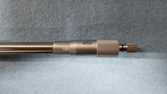
The micrometer stop isn't especially useful on a lathe with a DRO however there are times when the stop depth needs to be adjusted or refined so I made one. Inexpensive micrometer heads can he had for less than $20 so it was a no brainier to use one.

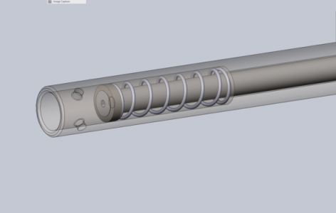
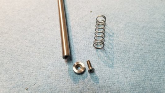
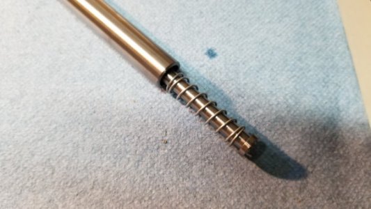
The tube is a piece of 1/2" DOM tubing with 0.120 walls. This gives a 0.260 inside diameter. There is some variation of the ID so I went with 15/64" drill rod for the stop rod. One end of the tube is drilled and reamed to 0.375" for the micrometer head and to a depth of 2" to allow for a spring that keeps the stop rod held up against the micrometer face. The micrometer head is secured with two 4-40 setscrews.

MicroStopAssm.png

20180304_090251.jpg
20180304_100703.jpg
20180304_101555.jpg
20180304_182757.jpg

For parts that need a larger diameter stop, simple collars can be made as needed to fit on the stop rod end.

20180304_121021.jpg

Lastly, because the stop rod is interchangeable I will probably make of a modular rod system at some point from 1/2" drill rod with a 1/4" dowel pin on one end. End stops of any shape/size can then be made as needed and secured to the dowel pin with a setscrew.

Modular Stop Rod.png

Thanks for looking.
 
Wholly C... really overbuilt, and over the top. But hey, it's a very cool way of doing it. Nice work.
 
Nice work Jay, clever design.
 
Awesome very well thought out


Sent from my iPhone using Tapatalk
 
Back
Top