-
Welcome back Guest! Did you know you can mentor other members here at H-M? If not, please check out our Relaunch of Hobby Machinist Mentoring Program!
You are using an out of date browser. It may not display this or other websites correctly.
You should upgrade or use an alternative browser.
You should upgrade or use an alternative browser.
The life of an old mill(K&T 2HL)
- Thread starter MrCrankyface
- Start date
- Joined
- Nov 7, 2019
- Messages
- 480
Thank you! I am not using ball screws but I hopefully will in the future.
I'm currently using the softwares backlash compensation and it works alright for light cuts and drilling. I wouldn't try to take a heavy cut tho, I'm sure the cutter would bite and pull the table/saddle off position.
Slowly making progress. Been so tired this week and wiring isn't the most exciting thing to do ...
I've started hooking up a VFD, gave it a testrun with a regular rubber cable and it works alright.
Pulls my RCD on the first startup though so I need to get that replaced to a type B apparently.
It's pretty neat seeing the machine start up smoothly over 2-3 seconds instead of just pulling a contactor and slamming into full speed..
The white contactor above will be controlled from the control panel to be able to shut the VFD on/off or let Mach3 automate it.
Waiting for the RCD to be replaced(hopefully today) and also some shielded cable between the VFD and mill to avoid electrical interference.
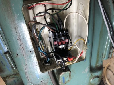
Found this in a closed box on the back of the mill when I was hooking up the VFD, look at that blue cable!
Not sure what's happened here but part of it has been overheated and insulation was VERY crispy.
Current-ish overview.
I'm currently using the softwares backlash compensation and it works alright for light cuts and drilling. I wouldn't try to take a heavy cut tho, I'm sure the cutter would bite and pull the table/saddle off position.
Slowly making progress. Been so tired this week and wiring isn't the most exciting thing to do ...
I've started hooking up a VFD, gave it a testrun with a regular rubber cable and it works alright.
Pulls my RCD on the first startup though so I need to get that replaced to a type B apparently.
It's pretty neat seeing the machine start up smoothly over 2-3 seconds instead of just pulling a contactor and slamming into full speed..
The white contactor above will be controlled from the control panel to be able to shut the VFD on/off or let Mach3 automate it.
Waiting for the RCD to be replaced(hopefully today) and also some shielded cable between the VFD and mill to avoid electrical interference.
Found this in a closed box on the back of the mill when I was hooking up the VFD, look at that blue cable!
Not sure what's happened here but part of it has been overheated and insulation was VERY crispy.

Current-ish overview.
Last edited:
- Joined
- Nov 7, 2019
- Messages
- 480
Progress is slow with lots of stress at work and autumn darkness isn't exactly boosting my energy either but here's what I've gotten done.
Had to install a seperate RCD for the VFD as the old one was no bueno.
It's now possible to start the PC, CNC PSU's and spindle from the control panel.
There's also the emergency stop to the far right which kills CNC PSU's and spindle.
Also added a USB receptacle for transfering cad/gcode stuff.
Everything is now prepared for LED lights around the spindle and some kind of cutting fluid pump.
I'm still not decided on wether I should go with just cutting fluid or have the option for pressurized air/mist cooler setup as well..
I've returned to working on the shields/doors which is starting to become more and more of a turd, no matter how much I polish it, it's still **** at the end of the day.
I will need to remake it completely in the second prototype but this will have to do for the moment as I'm out of energy for this part.
The window lifters work great but the door open/close is a nightmare, not to mention the lack of proper cable paths.
Cable attachments are very temporary since it will all be replaced.
For now I have disconnected the open/close mechanism and will do that manually.
"Shields" in versus out:
There will be a seperate piece in the middle but haven't started designing it yet.
Short vid of the lifters.
Last edited:
The K&T mills are very nice mills. I think they are still in business but not making mills anymore. I forget the details but remember investigating KT a few years back because one showed up locally. It too was a huge bargain. But I had to pass because it’s just too big of a machine for my limited space.
But they really made great mills. Not a machine that shows up a lot but very much a stout mill.
FWIW... if you ever need to move heavy stuff again...4 short lengths of 3/4 or 1” black iron pipe makes it real easy to roll stuff if you have a smooth concrete floor
But they really made great mills. Not a machine that shows up a lot but very much a stout mill.
FWIW... if you ever need to move heavy stuff again...4 short lengths of 3/4 or 1” black iron pipe makes it real easy to roll stuff if you have a smooth concrete floor
- Joined
- Nov 7, 2019
- Messages
- 480
Yeah this is pretty much a mini version so works in a garage. The bigger brother(2H) would be difficult to fit! 
Also pretty sure the concrete slab wouldn't like the weight.
Good tip!
I've come to the conclusion to remake the doors and lifters ASAP.
Got plenty of help with the 3D-CAD re-design from my new assistant.

Meanwhile I did a temporary solutions. The tinted window(protective plastic still on) is just placed into two holders, this locks the doors into position.
The switch on the control panel can raise/lower the windows at any time but it's not 100% reliable so sometimes you need to push one of the windows a bit.
Finally also got the control panel back in place.
I will let the machine produce one of the parts from plastic(HDPE I think) so this required me to finish the VFD install. Now the software can directly control the VFD's output so for easier work I can just leave the mill in top gear and let the VFD control the speed.
I've activated backlash compensation in Mach3 but either it's set wrong or my backlash is just too big to compensate because it doesn't come out right. Either way it's a constant learning experience!

Also pretty sure the concrete slab wouldn't like the weight.
Good tip!
I've come to the conclusion to remake the doors and lifters ASAP.
Got plenty of help with the 3D-CAD re-design from my new assistant.

Meanwhile I did a temporary solutions. The tinted window(protective plastic still on) is just placed into two holders, this locks the doors into position.
The switch on the control panel can raise/lower the windows at any time but it's not 100% reliable so sometimes you need to push one of the windows a bit.
Finally also got the control panel back in place.
I will let the machine produce one of the parts from plastic(HDPE I think) so this required me to finish the VFD install. Now the software can directly control the VFD's output so for easier work I can just leave the mill in top gear and let the VFD control the speed.
I've activated backlash compensation in Mach3 but either it's set wrong or my backlash is just too big to compensate because it doesn't come out right. Either way it's a constant learning experience!

Last edited:
- Joined
- Nov 7, 2019
- Messages
- 480
Starting working on this accessory attachment for the head the other day, using whatever scrap I had lying around..

Kinda going off the top of my head here as opposed to my usual routine of cadding everything up first.
Tried to get a rough shape of what I wanted first, limited by the material I had.
The horizontal plate was a bit flimsy despite being almost 1/4", it's from an old sign so probably very low grade aluminium. Bent this 'skirt' for it to also encase some lights.
Still struggling with AC TIG, I'm fairly sure a big part of the problem is not making sure the material is clean enough as it was impossible to keep the puddle clean.
Here's the 'final' outcome. The aluminium block can be raised and lowered with the red lever above to adjust for different size and length endmills.
The different tubes are air and cutting fluid, selectable from the control panel by one of the switches.
The block is a bit oversized at the moment but I will leave it like that incase I come up with some other ideas in the future.
This is the air supply I cobbled together, re-used stuff hence why the pressure meter only goes to 6 and not 10 bar as the compressor delivers.
After the pressuremeter is an electric solenoid and a pressure regulator.
Currently the solenoid gets a signal from the control panel directly, I might let the CNC control this itself in the future but haven't decided yet.
When in use I will connect the hose to the bottom of this rig.
The cutting fluid comes from this "tank".
Re-purposed can(what's the proper english term here?) with a level sensor(turns off pump is too low and gives alarm on the control panel).
The pump is a quite small diaphragm version but seems to do the trick, it's also controlled from the control panel for now.
The table drains into this outlet, I made a new piece to fit here so I could use a regular hose back to the tank.
It seals with an o-ring between the plate and the casting.
This was the first time I ground a HSS tool for putting in o-rings, spun the plate up in the lathe and just went for it.
Definitely fun trying new things!
I also managed to figure out the backlash issue! I measured the backlash 2 inch intervals along entire X and Y.
Not only were my steps per mm not calibrated well enough(It moved 607mm when I called for 600) but X-axis would also lose position sometimes.
I tracked the loss of position down to the big pulley not staying put on the shaft with only the grub screws so I opted to secure it with a through-pin.
Managed to slide-fit this bearing using just a small endmill, sure saves time when it's not a critical fitment!

The part I've been trying to mill belongs to the new door-opening assembly.
Definitely an overcomplicated solution, but fun and I'm learning a lot by doing it.

Kinda going off the top of my head here as opposed to my usual routine of cadding everything up first.
Tried to get a rough shape of what I wanted first, limited by the material I had.
The horizontal plate was a bit flimsy despite being almost 1/4", it's from an old sign so probably very low grade aluminium. Bent this 'skirt' for it to also encase some lights.
Still struggling with AC TIG, I'm fairly sure a big part of the problem is not making sure the material is clean enough as it was impossible to keep the puddle clean.
Here's the 'final' outcome. The aluminium block can be raised and lowered with the red lever above to adjust for different size and length endmills.
The different tubes are air and cutting fluid, selectable from the control panel by one of the switches.
The block is a bit oversized at the moment but I will leave it like that incase I come up with some other ideas in the future.
This is the air supply I cobbled together, re-used stuff hence why the pressure meter only goes to 6 and not 10 bar as the compressor delivers.
After the pressuremeter is an electric solenoid and a pressure regulator.
Currently the solenoid gets a signal from the control panel directly, I might let the CNC control this itself in the future but haven't decided yet.
When in use I will connect the hose to the bottom of this rig.
The cutting fluid comes from this "tank".
Re-purposed can(what's the proper english term here?) with a level sensor(turns off pump is too low and gives alarm on the control panel).
The pump is a quite small diaphragm version but seems to do the trick, it's also controlled from the control panel for now.
The table drains into this outlet, I made a new piece to fit here so I could use a regular hose back to the tank.
It seals with an o-ring between the plate and the casting.
This was the first time I ground a HSS tool for putting in o-rings, spun the plate up in the lathe and just went for it.
Definitely fun trying new things!
I also managed to figure out the backlash issue! I measured the backlash 2 inch intervals along entire X and Y.
Not only were my steps per mm not calibrated well enough(It moved 607mm when I called for 600) but X-axis would also lose position sometimes.
I tracked the loss of position down to the big pulley not staying put on the shaft with only the grub screws so I opted to secure it with a through-pin.
Managed to slide-fit this bearing using just a small endmill, sure saves time when it's not a critical fitment!

The part I've been trying to mill belongs to the new door-opening assembly.
Definitely an overcomplicated solution, but fun and I'm learning a lot by doing it.
Last edited:
- Joined
- Nov 7, 2019
- Messages
- 480
Managed to make some filler rod holders using the machine!
The thick white slab is machined in one go, terribly convinient.

I think total runtime was maybe 10 minutes, excluding tool swap time between drill and endmill.
The tubes are regular plumbing pipe, roughly 1.5" diameter.
Also started hacking together a cover for the X motor, probably among my worst welds I have ever made.
Between the lack of gas and extremely thin sheet(23 thou), it was overall a horrible experience but I was impatient to get it done.
Some grinding and paint will fix it up.
I started over on the doors, replacing the square tubing, painted the steel sheet and redesigned every plastic piece in one way or another..
Assembly is now smooth as butter and functions as it should.
Here's the completed setup.
The doors rotate out and raise the windows at the hit of a switch whilst the middle window is on a hinge and manually operated.
I skipped the doors folding in half, simply wasn't worth the mechanical complexity that it caused.
I also simplified the middle window with just a hinge, which works out well as when it's folded down, it protects the control panel really well whilst still letting you operate the switches.
Here's a short video earlier in the process, of one door opening and raising windows.
The thick white slab is machined in one go, terribly convinient.

I think total runtime was maybe 10 minutes, excluding tool swap time between drill and endmill.
The tubes are regular plumbing pipe, roughly 1.5" diameter.
Also started hacking together a cover for the X motor, probably among my worst welds I have ever made.
Between the lack of gas and extremely thin sheet(23 thou), it was overall a horrible experience but I was impatient to get it done.
Some grinding and paint will fix it up.
I started over on the doors, replacing the square tubing, painted the steel sheet and redesigned every plastic piece in one way or another..
Assembly is now smooth as butter and functions as it should.
Here's the completed setup.
The doors rotate out and raise the windows at the hit of a switch whilst the middle window is on a hinge and manually operated.
I skipped the doors folding in half, simply wasn't worth the mechanical complexity that it caused.
I also simplified the middle window with just a hinge, which works out well as when it's folded down, it protects the control panel really well whilst still letting you operate the switches.
Here's a short video earlier in the process, of one door opening and raising windows.
Last edited:
- Joined
- Nov 7, 2019
- Messages
- 480
The saga continues.
After testing the flood cooling a bit I realized there was a middle ground I was missing between air-blast and flood...
So I made and revised the cooling system with these pieces, lathed most of it from bar stock since that's what I had on hand.
The cooling pump will pump when either solenoid is on, one solenoid goes to flood and the other goes into the air-blast pipe, effectively making a mist-feature.
I finally went ahead and marked up the panel as well and added a small selector switch above the main control for coolant.
It will light up airblast/mist or flood depending on what it's set to, then you activate it with the bigger toggle switch.
Hopefully I can let the CNC activate this itself later on.
I've been letting it do some aluminium work and it's been a crazy amount of learning.
All tool paths has been generated by fusion360 and is hands down the most complex thing I have ever tried, although I'm sure it's absolute peanuts to people with the slightest bit of experience!
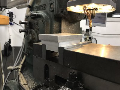
I believe the piece came out quite nice overall despite the little mistakes here and there.
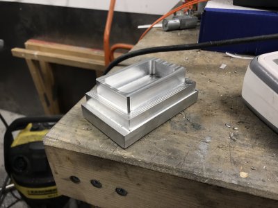
It's going to be a light fixture after some more work on it.
I've already started looking into ball screws as the current screws are highly limited when it comes to rounded paths.
Vibrations and end mill rotation can sometimes cause it to wander into the backlash area and remove material where it shouldn't.
This requires you to run very conservative cuts to avoid it.
This isn't news just stating the obvious
However ball screw conversion has to wait as this project has taken up too much time from other things that need doing.
What's left to do currently is mostly wiring jobs and screw the panel back into place.
-"error" wire from the stepper drivers so the entire machine stops if any of the stepper drivers gives out.(Almost need to swap pants when one driver faults and the rest keep milling...)
-Wires to each home sensor(I realized it'd be quite convinient to be able to set a "machine home" automatically)
-Extra wire to VFD to make sure it goes into FWD mode. Currently I have to climb behind the mill to go from "neutral" to fwd.
But once this is done it should be a very capable machine even without the ball screws!
After testing the flood cooling a bit I realized there was a middle ground I was missing between air-blast and flood...
So I made and revised the cooling system with these pieces, lathed most of it from bar stock since that's what I had on hand.
The cooling pump will pump when either solenoid is on, one solenoid goes to flood and the other goes into the air-blast pipe, effectively making a mist-feature.
I finally went ahead and marked up the panel as well and added a small selector switch above the main control for coolant.
It will light up airblast/mist or flood depending on what it's set to, then you activate it with the bigger toggle switch.
Hopefully I can let the CNC activate this itself later on.
I've been letting it do some aluminium work and it's been a crazy amount of learning.
All tool paths has been generated by fusion360 and is hands down the most complex thing I have ever tried, although I'm sure it's absolute peanuts to people with the slightest bit of experience!


I believe the piece came out quite nice overall despite the little mistakes here and there.

It's going to be a light fixture after some more work on it.
I've already started looking into ball screws as the current screws are highly limited when it comes to rounded paths.
Vibrations and end mill rotation can sometimes cause it to wander into the backlash area and remove material where it shouldn't.
This requires you to run very conservative cuts to avoid it.
This isn't news just stating the obvious

However ball screw conversion has to wait as this project has taken up too much time from other things that need doing.
What's left to do currently is mostly wiring jobs and screw the panel back into place.
-"error" wire from the stepper drivers so the entire machine stops if any of the stepper drivers gives out.(Almost need to swap pants when one driver faults and the rest keep milling...)
-Wires to each home sensor(I realized it'd be quite convinient to be able to set a "machine home" automatically)
-Extra wire to VFD to make sure it goes into FWD mode. Currently I have to climb behind the mill to go from "neutral" to fwd.
But once this is done it should be a very capable machine even without the ball screws!
Last edited:
- Joined
- Nov 7, 2019
- Messages
- 480
Finally got this video cut together.
It's part 2 out of probably 4, sums up a lot of the process better than I can word it.
It's part 2 out of probably 4, sums up a lot of the process better than I can word it.
- Joined
- Nov 7, 2019
- Messages
- 480
If anyone is following my threads, you can probably notice I'm all over the place right now.
Since the belt on the Z motor broke some days ago, I started thinking about regearing it.
The Z has always been a weak point, the motor often stalls out and moving it slowly (<10mm/min) was a sure way to cause it due to the axis being a bit sticky.
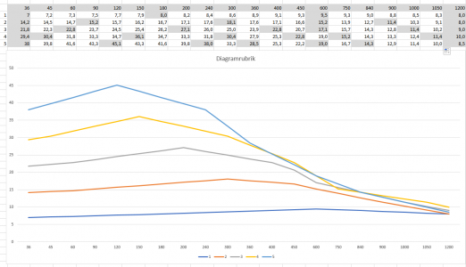
Following the datasheet speced at 60V AC, I've been calculating the torque over various gearings.
Torque in Nm on the Y axis and feeds in mm/min in the X axis.
Looking at this new graph, clearly a gear reduction of 4(yellow) to 5(light blue) times is MUCH better than the current 2:1(orange), I gain torque across the entire spectrum.
A 5:1 direct gear reduction would probably come out pretty huge so probably need to do a 2 stage gearing.
My goal is to make the Z speed reach 800mm/min, anything above that would be a great bonus, currently it maxes out at 300mm/min.

