- Joined
- Oct 5, 2010
- Messages
- 1,044
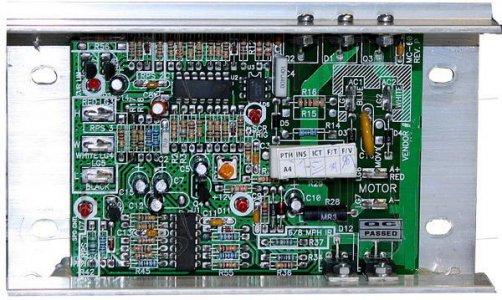
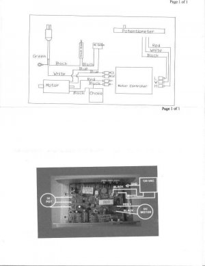
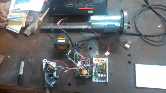
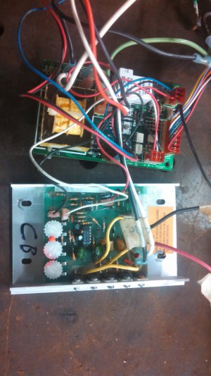
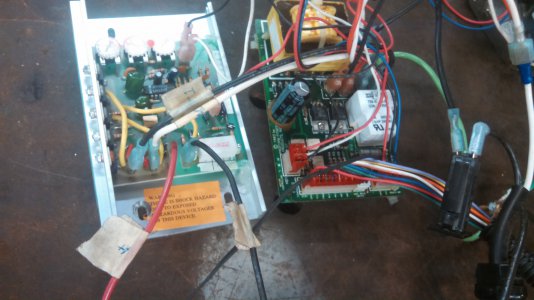
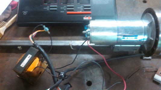
I have a 2.5 hp tread mill motor I have removed from a Weslow 890 treadmill. I have set the electronics on a bench. Basically it runs.
I first should interject that my electronics skills are very basic. I would like to use this motor on a belt grinder I am planning to build. I would like to use the speed control feature but have no use for the other functions.
As I said earlier, the motor runs but as the motor starts to speed up. It stops and I get an error code. I really don’t want the control panel that came with the treadmill. Does someone make a reasonably priced controller system that just allows me to turn it on and off and allows me to control the speed?
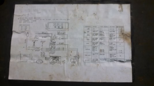
If there is no aftermarket controller. How do I disable the other functions from the controller board? At the moment it will not run unless the incline motor is hooked up.
What kind of max RPM should I expect to get from the motor? I sure never turned any high RPM on the tread mill.
TIA any help will be appreciated.
Randy


