Triggered Strobe

B

BRIAN

Forum Guest
Register Today
I intend to build a strobe light so I can balance the crank on my next project
I am thinking of using a pizio electric sensor to switch a LED light, some method of altering the sensitivity will be required
my electronics are not up to this so help is required to make the interface.
or any other ideas, It will be over a year before I need this .but a early start. will save time later.
Brian.
 
Check google Brian, there are a lot of them using a 555 timer and LEDs..

"Billy G"
 
Hi Billy
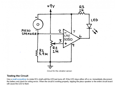
After a long hunt I finally came up with something similar to what I require. a strobe that fires once every time you make a input.
this was on the site of jame.com. the circuit is by Forrest m Mimms.
I need just enough light to read a protractor when the strobe fires one good LED will do it.I have also found a sensor that is more directional
and cheap. If I can get this package together some how it may work.
Brian.strobe2.PNG piezio.PNG
 
Hello,

I've been playing with a small led based strobe run by an arduino, i was using some low power white led's. Its's quite simple for timed flashes and things like that.

Although the 555 based variable speed could be handy and quick too.

Hobbyking have some 3w led's and other high power leds for quite good prices.

Do you want it to flash only when the beam brake(sensor) is interupted?

Stuart?
 
Hello Brian,

Interesting project sorry I can’t be much help on the electronics but will be following your progress since I’m always looking to learn something.

Many years ago I actually got a little hands-on use of a IRD brand portable strobe type balancing tool that used a piezoelectric accelerometer pickup. That tool is now obsolete and some would say primitive but was very useful. I have included a link below for the manual for that tool in case you can find it of use. Instructions for balancing start on page 4-19 of that manual.

http://www.atecorp.com/ATECorp/media/pdfs/data-sheets/IRD-880_Manual.pdf

Benny
 
Hi Stuart& Benny
Thank you for your input I will download the manual I am positive it will contain useful information.
The engine is a 5 cylinder radial, and when I have the crank case and internals done, the intention is to mount it on the mill with flexible mounts, and drive the crank through a universal joint.
attach a protractor to the crank with 0° at tdc No 1 attach the pick up to the case in line with No1.
Movement of the case will flash the strobe illuminate the protractor . this will tell me the direction of imbalance and if its positive or negative so I will know if I require more or less weight.
I know that the flash will possibly lead the actual high point so sensitivity control is required to limit that, then if the jig is run in reverse I can take the middle of the two readings.
My problem is I do not know enough about circuit design. and at 75 years of age I find It hard to remember what I already know, without learning a new subject.
Thanks again for your input. Brian
 
Wow!!! Benny that strobe is way beyond what I am looking at, Very interesting.
What I require is more along the lines of a car wheel balancer, simple but effective.
Brian.
 
I have no idea of the original circuitry. Maybe googling will help....

At my uncle's auto shop in the 1960's, he had a tire balancing machine that had dials on the right and left.

An arc would jump at the angle facing the operator. IIRC the angles were numbered only to 20 around a complete circle.

The spindle for the tire was numbered similarly. The operator adjusted the sensitivity on each side. The machine showed where around the tire was the heavy spot and on which side.

From the amount of movement a weight was chosen and installed 180* opposite the indicated position. Then re-spun.

I've used a timing light many times too.

So, looking at what you are trying to accomplish.....

As your experimental device spins, it will move outward in the direction the heavy spot is pointing at the moment.

The protractor will be attached to the spinning shaft with the adjustable (for sensitivity) sensor mounted solidly at zero degrees.

When the case moves sufficiently towards the sensor, the light will flash. That will reveal where on the shaft is the heavy spot.....

Ah! You need a solid pointer with the sensor and the LED must illuminate the pointer as well as the protractor. Got it!

Your sensor can be as simple as a screw inside a nylon nut. Insure the crankcase is grounded and run your sense wire to the screw. When the crankcase moves sufficiently towards the screw, an electric circuit is completed to ground. Flash the light! You can use the cross-slide as the adjustment.

Whatcha tink?
 
Hi Mike
This would certainly indicate any of the visible out of balance. the amount of case movement being dependant on how soft the mounts on the test rig are
I think a spring loaded pickup pointer is necessary just in case it gets a thump.
The light will not have to be high power a small cheap flash light with a single LED will do, just bring the contacts out of the case. the power required is so small the contact points will not suffer from burning, I have a top slide and angle bracket that will serve as an adjustment.
On thinking about it the final engine mount will be solid and the mass of the complete motor a lot higher so any remaining vibrations may be damped out.
I may do some tests to get more data. after all it's no going to cost a lot of green stuff
Regards Brian

The amount of case movement will be dependent on the softness of the mounts and the amount of movement they allow. And more importantly, how badly the crankshaft is out-of-balance. As you get closer to 'perfectly balanced' the amount of x, y and z motion will be reduced for a given speed.

Your idea that you need a strobe light is quite valid. Persistence of vision only works for a flash of light. So you'll need a shaded "beam" of light that is on for about 1/30-1/24 of a second that will light the protractor and pointer. You'll want a mains powered power supply to minimize recycle time.

Since only trigger power will cross the contact points, there should be no burning/arcing. The trigger voltage should be kept very low (under 5v) and be DC to avoid delays from the AC sine wave.

The sensor should be mounted solidly to the adjuster. On initial spin-up the sensor shouldn't be on the test rig at all. Once you are satisfied that the crankshaft will spin at a reasonable speed and not tear the test rig apart. Mount a crayon about where the sensor will go. Spin it up, extend the crayon slowly. Once you get contact, you have your starting gap. Shutdown and mount the sensor.

We are getting a bit ahead of ourselves, aren't we? Have you built the crankshaft yet?
 
Back
Top