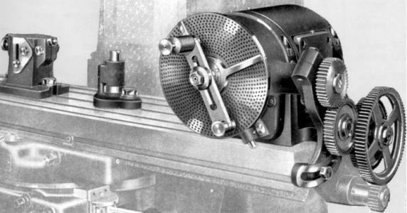
VN Universal sub-head on ebay

Reeltor

Active User
Registered
Joined
Nov 18, 2014
Messages
741
Universal sub-head for VN

I saw this listed this morning, and I'm wondering if the seller's claim is correct.

The owner claims
: "Used in conjuction with a lead screw coupled dividing head to position the cutter at the correct lead angle for spiral milling without a universal saddle."

Is this correct? Will you be able to do spiral/helix milling with a universal sub-head (and a universal dividing head) on a standard table mill?
This one won't fit my mill. If true, I'll need to start looking for one for a 22.

eBay item number:

321654362727

$_14.JPG

$_14.JPG
 
Last edited:
Re: Universal sub-head for VN

I
The owner claims
: "Used in conjuction with a lead screw coupled dividing head to position the cutter at the correct lead angle for spiral milling without a universal saddle."

Is this correct? Will you be able to do spiral/helix milling with a universal sub-head (and a universal dividing head) on a standard table mill?
This one won't fit my mill. If true, I'll need to start looking for one for a 22.

Yes. The claim is correct.

The "challenging part" however is arranging or finding a drive solution that links the feed axis to the dividing head. The VN heads {perhaps
most heads like the more commonly found Cincinatti} have the ability to be driven through a right angle shaft with a
gear that protrudes through the base.

Van Norman made a small open transmission that replaced the feed dial and handle on the X axis of a #12. It had
interchange gear sets allowing various thread pitches.
universal-head-drive.png
The universal head just provides the pitch angle with straight cutters -- in lieu of using a cutter tapered to the angle.

I've been collecting the hardware to make a digital drive for my 10" VN head; an encoder that mounts on the X {or Y
even!} shaft; PWM supply; and stepper motor that directly drives the head. Most of my needs are for drilling bolt circles
but with a "reasonable" supply and motor one could consider spiral milling using a similar setup. The advantage is
merely "no change gears" to mess with.

The disadvantage is the need to "lock" the head to withstand "polar" side loads
encountered in milling. The VN head uses a simple friction clamping/stop pin arrangement -- so not a very stout lock.
"Back driving" interia/torque from the change gears helps stabilize the head in this regard.

--frankb

universal-head-drive.png
 
Re: Universal sub-head for VN

Yes. The claim is correct.

The "challenging part" however is arranging or finding a drive solution that links the feed axis to the dividing head. The VN heads {perhaps
most heads like the more commonly found Cincinatti} have the ability to be driven through a right angle shaft with a
gear that protrudes through the base.

Van Norman made a small open transmission that replaced the feed dial and handle on the X axis of a #12. It had
interchange gear sets allowing various thread pitches.
View attachment 93659
The universal head just provides the pitch angle with straight cutters -- in lieu of using a cutter tapered to the angle.

I've been collecting the hardware to make a digital drive for my 10" VN head; an encoder that mounts on the X {or Y
even!} shaft; PWM supply; and stepper motor that directly drives the head. Most of my needs are for drilling bolt circles
but with a "reasonable" supply and motor one could consider spiral milling using a similar setup. The advantage is
merely "no change gears" to mess with.

The disadvantage is the need to "lock" the head to withstand "polar" side loads
encountered in milling. The VN head uses a simple friction clamping/stop pin arrangement -- so not a very stout lock.
"Back driving" interia/torque from the change gears helps stabilize the head in this regard.

--frankb

Frank,

I have the universal dividing head and the enclosed gear box (I don't have many change gears to set the proper lead). Here is my question, and perhaps you answered it but I'm too dense :whistle:
The attachment is for the head and setup that I have, it states that the gear train is used on universal mill tables. Does the subhead eliminate the need for a universal table?
View attachment page 2 of ATTACHMENTS ARBORS AND ACCESSORIES.pdf

Your digital head sounds great, I'd like to see it in operation when you get it finished.

Mike
 
Re: Universal sub-head for VN

Mike

The attachment is for the head and setup that I have, it states that the gear train is used on universal mill tables.
Does the subhead eliminate the need for a universal table?

You "attached" a file showing a swivel dividing head and an enclosed gear box. I think the original question was:
"do I need a sub-head?". It would help {me} if you would re-phrase your question still using "sub-head" as one of the query
targets. The document doesn't say a universal table is required to spiral mill; it says "it only fits a universal table".

Two different issues arise:

1) can it do the work?

2) will it fit my setup?

The sub-head "just" gives you an angle adjustment -- at a right angle to Y. Otherwise you're limited to cutting keyways -- although they can be
"spiral keys" with an X axis setup of the DH which is technically an acme/scroll thread -- right?

So depending on what you mean by "spiral milling" -- acmes; splines; scrolls; and splined tapers {think "E Z Out"}
all come to mind as possible applications of spiral milling; different setups are required
-- one might/might not require a sub-head.

For instance a face scroll {like a chuck jaw backing plate} is produced with a Y axis orientation of the 'stock head+ divider'.
No subhead required. No tailstock possible obviously. And since the DH can only be driven by the X axis you have to think
about moving the dividing head into a Y axis orientation -- while keeping its drive spindle on the X axis. {Some VN
DH's have a base that rotates.}

{ I should note that I'm aware there are a lot of other things one can do with a dividing head/subhead combo -- but I'm addressing the
perceived query "why a sub-head?" when I wrote "just .. an .. angle" -- and also assuming the subhead has a quill.}

--frankb

More than you wanted to know or ask perhaps. Introducing three additional setup angles and two more drive axes into the typical
"very flexible" VN makes for a dizzying array of geometry possibilities and constraints to plan .... typical of five axis machining problems.
 
Last edited:
Frank,

Poor question structure on my part.

The subhead in the ebay ad is for a 12 or 16 machine, I have a 22 but wanted to know if the proper subhead for the 22 would allow me to cut helical gears on a standard table machine.

http://youtu.be/tePh773MxNA

I've added a YouTube video of someone using a horizontal setup to cut a gear.

You hit the nail on the head by questioning what is meant by spiral. I read spiral but thought helical :nuts:
 
... wanted to know if the proper subhead for the 22 would allow me to cut helical gears on a standard table machine.

http://youtu.be/tePh773MxNA

Mike

Nice choice of video. But I think the "setup challenge" is easier to get {my/your} head around if you view this one:

https://www.youtube.com/watch?v=blaZ5tz0_6E

It shows the basic requirements for milling a helix:

A) Inclination between the rotating axis of the part and the rotating axis of the tool; "helix" angle

B) a means of driving the part smoothly through its polar rotation; and indexing for the next tooth setup

In the video you chose it just wasn't as easy to see the polar rotation while milling. But --clearly-- the
helix angle was setup on the rotary axis of the universal table.

Using the DH driven on the X axis has the "limitation" of constraining part rotation to be along that axis.
But we could also rotate the spindle axis w.r.t. the part and achieve the same angle -- right? This is one
"possible setup" of a subhead.

Here's a helical milling video using a subhead in that "angled spindle" position:

https://www.youtube.com/watch?v=L18a_wfaRBE

I think this is very close to what you desire; and is made feasible by orienting your spindle head on vertical axis and
rotating the subhead to the helix angle. This removes the requirement to "helically orient" the X axis -- allowing you
to use it square to the main drive axis. In other words no universal table is required.

---

Like the second video I hope to drive my DH with a servo motor {a stepper is a cheap test prototype}; which
enables me to mount it atop a rotary table to get the same helix angle introduced into a non-universal table.
But I think your question is answered for "certain" helical parts.

IF there is a "downside" of doing it this way its that the clearances required are more easily lost to the bulk of
the subhead. And the setup has to be "single ended" -- losing the rigidity of the tailstock.

Hope I got this right.:talktogod:

--frankb
 
:thankyou:
Thanks for searching out the videos, they really helped getting the orientation straight (or should I say at 10*?).
Yes, I think you have it right :))

Mike
 
Re: Universal sub-head for VN

{I should note that I'm aware there are a lot of other things one can do with a dividing head/subhead combo ......}

I've been following this thread.

franklynb,
I'd appreciate if you would please elaborate on the dividing head/subhead combo.
I've been running a VN6, with a 6inch Grizzly RT, index plates, and tailstock.
And am tooling up a VN22LU. I've picked up a VN swivel dividing head, matching tailstock, and 9 of the 11 gears.
I expect I'll be trying to fab the DH X axis gearbox.

I've always considered gear making as the holy grail of machining.
If you'd have an opportunity to share your insight and experience that'd be really helpful.
I'm having difficulty finding appropriate texts for anything beyond the basics.

Thank you!!
Daryl
MN
 
Re: Universal sub-head for VN

I'd appreciate if you would please elaborate on the dividing head/subhead combo.
I've been running a VN6, with a 6inch Grizzly RT, index plates, and tailstock ....
Daryl

Hi Daryl.

I wanted to take a day or two to frame some thoughts. I'm no expert. I've had the luxury of both a
formal and "hands-on" machining education. I'll try not to get dragged into debating "my opinions".

1) The hardest part I ever had to make was an oval. In my mind its way tougher than any gear.

{It was a hand knob re-design for a turret lathe early in my engineering career. The task of developing a
design and production process was given to me -- as a test -- by my boss; who wanted to gauge
my familiarity with tool room methods and practices.}

Beziers {compound curves in one to many planes} "drag you into" dead zone; repeatibilty; backlash;
error measurement; and radial resolution {not to be confused with precision} issues in a way that few
linear part features ever will.

2) A dividing head has ONE feature that improves it over a simple rotary table; coincident action w.r.t
its drive axis. That assumes its used to create "concurrent" axis motion between its polar and lateral axes.
Rigging a rotary table to perform this task "requires" some sort of computer numerical control of the polar axis --
or a change gear transmission of similar/greater complexity Part of the transmission is "built-in" to many dividing
heads.

3) Polar machining is made more difficult by lack of space for a 'decent' linear vernier. I once bought a radial optical
comparator table from a grinding shop the did ~2" parts. The vernier on the table -- used for photometric comparison of
angles -- was 24" in diameter! Hairlines can only be so thin -- and still be useful. It is also quite tough to do "odd"
partitions {7ths; 13ths} using a linear vernier. So making the vernier "wheel" REALLY large when compared to the
workpiece is one way of solving the radial resolution problem.

Fabricators of large parts do this all the time. I've seen errors on frames of buildings approaching "horrific" because
the contractor didn't know enough to project his layout lines a reasonable distance. Framing a 48 inch wall
at 82 degrees can be fraught with errors at "tape measure" accuracy. If you project the string out 20 feet the
1/8"? 1/16"? tolerance zone is 1/5 the angular error!

So a dividing head gives us the capability to rotate part features a known and precise radial distance -- in a relatively
compact package
. For the same reason we use lead screws -- to get the vernier to rotate a reasonable distance
for the spacing/movement required. This improves the resolution of the vernier. Resolution is one important component of
precision.

So while I have a rotary table; in many cases its just plain easier to get the radial resolution on a '40:1 geardown' DH. I can move
a DH 1/4 of a degree in two seconds {one pin hole on a 36 segment wheel}. Using an RT radial vernier I can get it CLOSE -- but its really
limited by table size. And if the vernier has a 10:1 hash -- pretty standard -- I must INTERPOLATE the halfway mark between the .2 and .3
hash mark to get one quarter of a degree!

---

Three axis milling is constrained by the need to rotate the tool. So at every step you have to deal with the fact that there is little
correspondence between the shape of the tool tip and the part feature. {End mills don't just make holes.}
Unlike a fixed tool {lathe; shaper; broach etc} where the shape of the tool tip is "inherited" by the part one must always reconcile the
presentation of tool --with all its motions-- to figure out what the resulting part feature becomes.

A sub-head -- in my mind -- is just one more "degree of freedom" for the presentation of the tool to the workpiece. Since milling is fraught
with competition between work surface and work-holding features that 'degree of freedom' takes on a particularly special significance --
there are places where it will ENABLE us to make the part feature that could not otherwise be reached. Or to a level of coherence that
might otherwise be compromised.

So in my thinking about "auxiliary axes" I tend to get VERY 'part feature specific' and then try to generalize the set of features into a
known vocabulary of names for their "container" parts -- NOT the other way around.

So its hard for me to think about "gears" as a class of entities without de-constructing the class to its component features.
IOW I cannot say anything "in general" about the usefulness of a sub-head 'for making gears'.

BUT if you want to talk about making 'ramped fillets' -- we can readily contrast and compare sine block setups and their accuracies
{one method of setting up a ramp} with the vernier {another method} type resolution of a sub-head. And perhaps explore methods for setups
that take us to "the next level" of accuracy on a sub-head setup -- something more like 1/10th of a degree rather than the interpolated 1/2 degree
that most offer. Its a "feature orientation" that allows us to compare apples and apples.

After 45 years of making "special" parts; finding/fixing other people's setup and machining errors; designing trick stuff for a living in various domains;
I could go on and on -- if you think this brief note doesn't do that.

hope this starts a good conversation. as always YMMV.

--frankb
 
Re: Universal sub-head for VN

I wanted to take a day or two to frame some thoughts. I'm no expert. I've had the luxury of both a
formal and "hands-on" machining education. I'll try not to get dragged into debating "my opinions".

1) The hardest part I ever had to make was an oval. In my mind its way tougher than any gear.

{It was a hand knob re-design for a turret lathe early in my engineering career. The task of developing a
design and production process was given to me -- as a test -- by my boss; who wanted to gauge
my familiarity with tool room methods and practices.}

Beziers {compound curves in one to many planes} "drag you into" dead zone; repeatability; backlash;
error measurement; and radial resolution {not to be confused with precision} issues in a way that few
linear part features ever will.

This makes sense after I read it about eight times. I've never heard of a Bezier. Thank you!


2) A dividing head has ONE feature that improves it over a simple rotary table; coincident action w.r.t
its drive axis. That assumes its used to create "concurrent" axis motion between its polar and lateral axes.
Rigging a rotary table to perform this task "requires" some sort of computer numerical control of the polar axis --
or a change gear transmission of similar/greater complexity Part of the transmission is "built-in" to many dividing
heads.

Does this include RT with indexing plates?

3) Polar machining is made more difficult by lack of space for a 'decent' linear vernier. I once bought a radial optical
comparator table from a grinding shop the did ~2" parts. The vernier on the table -- used for photometric comparison of
angles -- was 24" in diameter! Hairlines can only be so thin -- and still be useful. It is also quite tough to do "odd"
partitions {7ths; 13ths} using a linear vernier. So making the vernier "wheel" REALLY large when compared to the
workpiece is one way of solving the radial resolution problem.

This makes complete sense (I only read it twice!). It's a concept I'm familiar with from metrology texts I've found online.

Fabricators of large parts do this all the time. I've seen errors on frames of buildings approaching "horrific" because
the contractor didn't know enough to project his layout lines a reasonable distance. Framing a 48 inch wall
at 82 degrees can be fraught with errors at "tape measure" accuracy. If you project the string out 20 feet the
1/8"? 1/16"? tolerance zone is 1/5 the angular error!

So a dividing head gives us the capability to rotate part features a known and precise radial distance -- in a relatively
compact package
. For the same reason we use lead screws -- to get the vernier to rotate a reasonable distance
for the spacing/movement required. This improves the resolution of the vernier. Resolution is one important component of
precision.

This also makes sense. Spindle metrology, and the leadscrew precision are critical factors. Moores books have helped me appreciate leadscrew precision.

So while I have a rotary table; in many cases its just plain easier to get the radial resolution on a '40:1 geardown' DH. I can move
a DH 1/4 of a degree in two seconds {one pin hole on a 36 segment wheel}. Using an RT radial vernier I can get it CLOSE -- but its really
limited by table size. And if the vernier has a 10:1 hash -- pretty standard -- I must INTERPOLATE the halfway mark between the .2 and .3
hash mark to get one quarter of a degree!

Understood. If your RT has an index plate option is this also accurate?

---

Three axis milling is constrained by the need to rotate the tool. So at every step you have to deal with the fact that there is little
correspondence between the shape of the tool tip and the part feature. {End mills don't just make holes.}
Unlike a fixed tool {lathe; shaper; broach etc} where the shape of the tool tip is "inherited" by the part one must always reconcile the presentation of tool --with all its motions-- to figure out what the resulting part feature becomes.

A sub-head -- in my mind -- is just one more "degree of freedom" for the presentation of the tool to the workpiece. Since milling is fraught with competition between work surface and work-holding features that 'degree of freedom' takes on a particularly special significance -- there are places where it will ENABLE us to make the part feature that could not otherwise be reached. Or to a level of coherence that might otherwise be compromised.

Thinking in 3 dimensions is the critical factor. Adding another variable is intriguing, albeit potentially overwhelming. I'm also fascinated by the introduction of error secondary to poorly designed/maintained/tired tooling. Mores specifically how the veteran machinist anticipates and overcomes this potential obstacle with consistent results.

So in my thinking about "auxiliary axes" I tend to get VERY 'part feature specific' and then try to generalize the set of features into a known vocabulary of names for their "container" parts -- NOT the other way around.

So its hard for me to think about "gears" as a class of entities without de-constructing the class to its component features.
IOW I cannot say anything "in general" about the usefulness of a sub-head 'for making gears'.

Hmmm. Likely it's appropriate to think about the individual and specific features of a part more than the part as a whole. This is not only appropriate for making the part. But also, for problem solving the realization of any given feature (eat an elephant one bite at a time).

BUT if you want to talk about making 'ramped fillets' -- we can readily contrast and compare sine block setups and their accuracies
{one method of setting up a ramp} with the vernier {another method} type resolution of a sub-head. And perhaps explore methods for setups that take us to "the next level" of accuracy on a sub-head setup -- something more like 1/10th of a degree rather than the interpolated 1/2 degree that most offer. Its a "feature orientation" that allows us to compare apples and apples.

I'm lost on this paragraph. Likely I need to read up more on sine theory. I'm lost on the concept of a vernier ramp.


After 45 years of making "special" parts; finding/fixing other people's setup and machining errors; designing trick stuff for a living in various domains;
I could go on and on -- if you think this brief note doesn't do that.
hope this starts a good conversation. as always YMMV.

I have much to learn. Thank you for taking time to write this! Daryl MN

--frankb
 
Back
Top