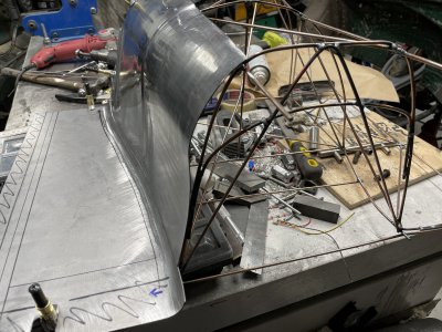
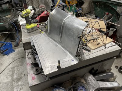
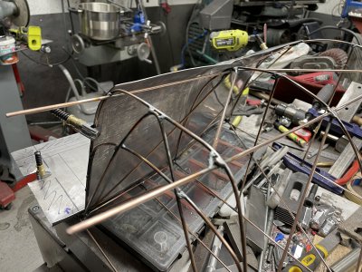
Volvo Amazon 1965 (Volvo 13134)

Trying to not overdo it since my elbows are about to explode from all this manual labour, definitely not used to all this wheeling, manipulating and hammering.
Made a rough mirrored piece to the first part, for the drivers side.
The perimeter is a bit different since the surrounding sheet is cut a bit different so it looks more "off" than it really is.
IMG_8501.JPG

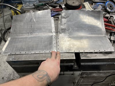
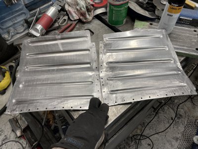
Decided to beadroll it like this, as deep as possible with the widest wheel I had.
My beadroller, despite looking quite stout, definitely did NOT like this.. :grin:
Not only did the wheels have a tendency to slip sideways and not stay where I set them, causing varying widths on the beads, but the frame also kept twisting a bit out of alignment causing one wheel to go ahead of the other.
Definitely need to weld on some more material if I want to keep rolling 1.25mm sheet(I know it's quite thick for work like this).
IMG_8505.JPEG

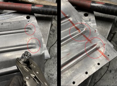
I "coined" all the beads as shown in the previous photo. Never tried this before but got inspired by some youtube video.
Gave it a quick "hack level try" by grinding out a socket and cutting half off as I didn't feel like starting the lathe and making tools.
The socket was surprisingly soft and quickly deformed from the hammer blows but it did it's job on the sheet.
Even tho the result is far from perfect I still prefer it to the "un-coined" beads that just smear back into the main sheet where they end.
Definitely need to make a proper tool that's easier to use, with this setup I was trying to hold the sheet with my hip, socket with left hand and hammer with my right hand, hence all the weird marks where they shouldn't be.:grin:
IMG_8502.JPEG

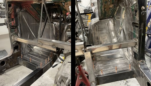
And this is what the inside looks like now.
I didn't pre-stretch before I beaded them which caused a lot of warping, definitely need to pre-stretch when you've already meticulously shaped the pieces to fit perfectly...
Caused quite a bit of work afterwards with hammer and "hand manipulating" to get it to fit. It's not as good as it was before but still fits in pretty OK.
Most of the clecos sit in 3mm holes in both plate and frame and only required a little force to get all of them in.
Pretty stoked about finally having a little bit of floor after almost 3 years or something. :grin:
IMG_8507.JPG
 
Thanks!
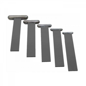
I've seen those and the bent versions, would love to have them but quite pricey for what they are unfortunately.
I think they would help a little bit but you'd have to manipulate a lot with the hammer.
I.e put the dolly on the concave side and then try to use the hammer and end radius of the dolly to massage it around.

What the coining tool lets you do is put the sheet flat against something, align the radius of the tool against the end of the bead and just hammer it down flat against the flat surface underneath, a bit more straight forward I think.
I think using the dollies backwards would not result in a 'sharp' edge as the metal around it would also tag along and stretch out.

Those dollies would however be excellent for adjusting the beads so they're more uniform!
 
okay, now I get it...... your tool is used on the raised side to "finish the end" of the raised section.
You are right much easier against a flat surface.

Brian
 
Exactly! Hard to explain in words. :grin:

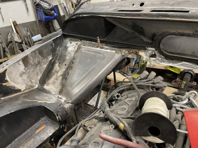
Made another little panel and covered up a half-hole next to it.
Flat panels are boring and I didn't want the "normal" beads here. The other engine bay panels seem to mostly utilize different versions of steps so I tried to recreate it somewhat. Definitely need to go over this with a dolly later to fix some uneven parts.
IMG_8513.JPGIMG_8514.JPG

And just to show that even with "years of experience" you can still goof up. :grin:
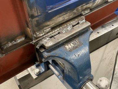
I was modifying the english wheel again, reinstalling the rack for the extra wheels and adding a strip along the bottom so it rests on the vice before you clamp it.
WELL ... My visor is so dirty and scratched that I couldn't really see where I was going, suddenly I've welded the wheel frame to the vice. :grin::grin::grin:
IMG_8518.JPG

Either way whilst dealing with that side project I also need to deal with the bead roller.
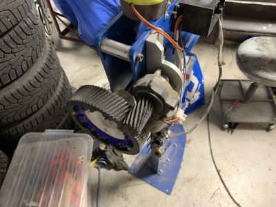
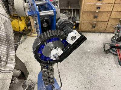
It has had a tendency to skip teeth when trying to do too much at once and now with the thicker steel for the floor/firewall it's been an absolutely agony to work around.
A large part of the problem is the thin motor axle and a lot of extension on both the motor and bead rollers axles, causing the axles to bend away from each other and the gears skipping.
Surprisingly the gears have held up remarkably well for years despite this abuse.
IMG_4960.JPG

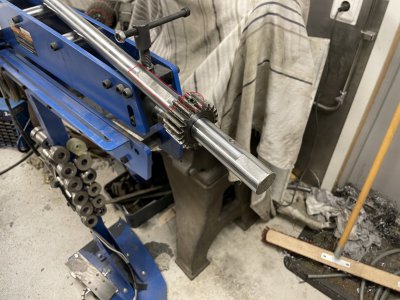
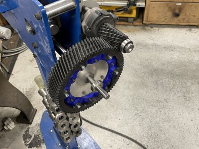
I haven't really thought about how the beadroller works mechanically before but it's high time considering that I need to take out the entire axle to modify it.
One "interesting" part is how the gear syncing to the other axle is just held on by a grubscrew, and was quite loose...
I would like to replace this with a proper key but don't really have the tools for it at the moment and the key might also increase the risk of cracking the gear so it's a risky maneuver.
The large plastic gear used to sit on this side.
The end needs to be squared up(it's rough saw from factory) and extended somehow.
IMG_8519.JPG

The motor gear also needed a longer axle, which I didn't have and is a weird hexagon type, so I'm taking a risk of just pushing it through further so it pokes through the other side.
I'm "guesstimating" that this won't matter much.
The axle will have less area inside the motor to apply it's forces against but it's still several centimeters deep, and I'm fairly certain that only the first centimeter or so sees the largest forces.
I worked down the hexagon to be round and ended up with the weird-ish dimension of 5.85 mm. It would've been easier to sleeve this if I went to 5.00 but I didn't want to slim down an already slim axle.
IMG_8521.JPG

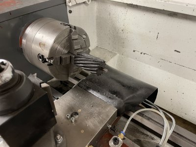
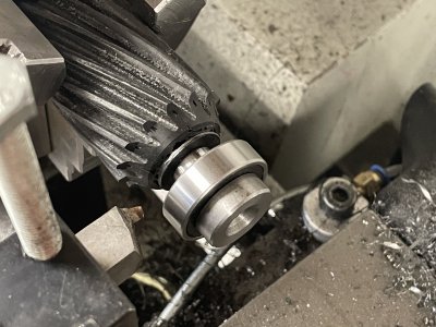
For the sleeve/spacer I drilled it out to 5.5mm and then made a absolutely ridiculous boring bar which worked surprisingly well to get it up to ~5.8mm, giving me a slight press fit of 0.05mm.
To get some clearance around the bearing(bit of an afterthought) I had to cut down the gear a bit.
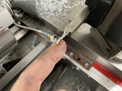
Since it's printed plastic I was slightly worried about de-lamination from the intermittent cuts.
I ground and polished a little HSS tool which did an amazing job at this.
Unfortunately I went a bit too far in places so there's some holes but this won't matter functionally.
IMG_8523.JPGIMG_8526.JPG

So the thick shaft was drilled out and reamed to 12mm, a linear rod has a tight sliding fit.
I was hoping for a press fit but achieved this by center punching the rod as it was midways inserted through the hole for the locking pin(right picture, in the transparent section). This locking pin both keeps the assembly from sliding off and locks the gear and both shafts together.
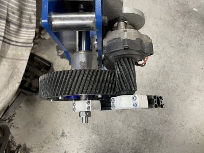
Printed some bearing holders and attached them with T-nuts to some aluminum extrusion.
Since the motor mount is adjustable in height for different gear ratios, the supporting bracket also needs to be adjustable hence the T-nut solution.
Further more the combination of plastic and aluminum makes this just stiff enough to work or rather just weak enough to not cause problems.
The whole assembly is no wonder of precision, where even the main shaft lies in bushings that easily has 1mm of play, so the idea is that a slightly flexible mount will take up any errors without binding things up too hard.

I've run it for a few minutes and seems to work well, there's a slight oscillation in the motor gear which I suspect is just the shaft being a bit bent, this gets taken up quite well by the reinforcing bracket.
Should definitely make it a lot more fun, productive and easy to make panels.
IMG_8528.JPGIMG_8529.JPG

Furthermore the frame was actually twisted a bit. I released all the bolts holding the two halves together and then used clamps to force them back and then some extra before re-tightening.
This took all the twist out but we'll see if it holds or if I need to weld/bolt in some reinforcing plats to take up the twisting forces.
 

Attachments

  • IMG_8525.JPG
    IMG_8525.JPG
    514.2 KB · Views: 2
Been going back and forth how to proceed with the sheet work.
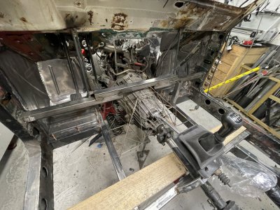
Struggling to visualize how I want to do the center of the firewall so I figured I'd start on the driveshaft tunnel and see where things naturally meet up.
But to do the driveshaft tunnel I need to know where the shifter will sit, and on it goes.
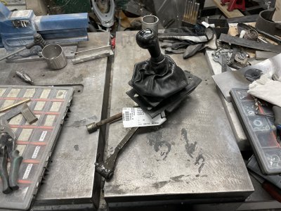
Long story short, I ordered a shifter assembly that fits this gearbox, arrived dirty as heck. :grin:
IMG_8545.JPG

Kindly enough the dealer/scrapper even included all the bushings, nuts and bolts so I could quite easily attach everything.
I did start by taking the entire assembly apart and cleaning it, apparently there was gray aluminium under all that black grease and soot. :D
The actual shifter rod is quite rusty so might need to run that through the wire wheel
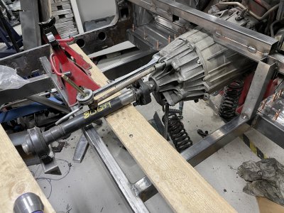
The rod extending backwards, along the driveshaft, is meant to sit in some kind of bushing, without it the entire assembly is free to move up and down.
IMG_8547.JPG

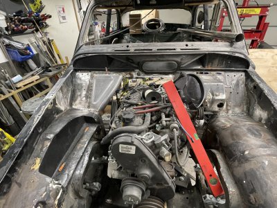
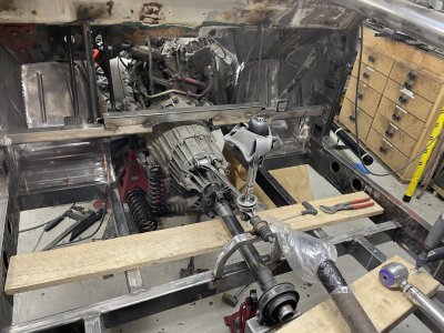
Decided to shoot from the hip and started making some kind of combined driveshaft catcher(if it breaks), shifter mount and driveshaft tunnel reinforcement.
Started out with a scrap piece of 20x20 tube and followed up by a lot of cutting, bending, welding and grinding.
I managed to twist the entire cross-section so the driveshaft tunnel will sit flat on it as it narrows down a bit towards the back, it's very slight but I think it will help a lot with the sheet work later.
The bushing piece sits ontop of this and the driveshaft goes through the center, might need to do a little cutout in the lower beam but that's for later.
IMG_8553.JPG

With the shifter placed I should be ready to start making some more sheet pieces.
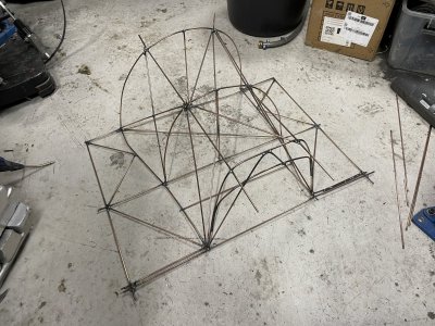
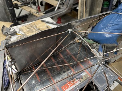
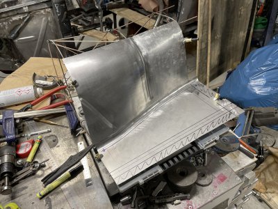
Since the shape is pretty annoying I'm again trying to use a wirebuck.
Found a cheaper source of rod for it, regular TIG filler rod, works great!
The idea is to place the sheet on top of this buck, there's some reinforcements preventing this but those are temporary.
Once I take the buck out of the car I will reinforce it through where the gearbox currently sits, and then remove the external reinforcements that are in the way.
IMG_8559.JPG
 
Got the buck out of the car and reinforced in a way that's useable.
IMG_8570.JPEG

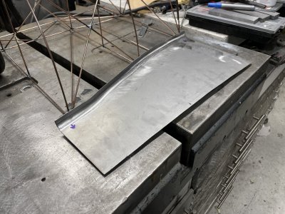
First floor piece was relatively easy. Beadrolled the radius and used the shrink/stretcher to make the panel flat again.
IMG_8579.JPG

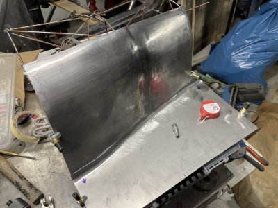
Been struggling with the next piece for a few hours now. Trying to get the concave shape to stretch upwards but it's being extremely stubborn.
In my mind there's too little material, keeping it tight, like pulling on a rope.
To get the "sunk in" shape I want, I need to stretch the material out along the middle to get it to relax against the buck more.
Judging by how the perimeter at the top/middle is bending away from the buck I suspect it will work but I need to stretch a lot more below the perimeter to get it to curve back down.
Gotta do some trial and error next session.
IMG_8583.JPG
 
Spent an hour or two yesterday(trying to keep the sessions short since my elbow and wrist are doing something weird).
I did try more wheeling but nothing I do seems to change the shape of the bulge above the "sinkhole", I do however notice flex in the wheel frame.
I suspect the combination of thick steel and my flimsy wheel is prohibiting it from being able to push more stretch into this part.

I tried the planishing hammer setup instead but can't seem to get it to strike hard enough either, not sure if my hammer is defective to be honest since it seems quite weak overall when I compare to other peoples(youtube) videos who have the same type of air hammer.
For a while I wondered if the frame was too flimsy for the hammer as well but from what I can find online they work well even with very flimsy frames, much flimsier than mine. Tempted to open the hammer and see how it works and if there's any way of improving it's performance..

Only way I managed to get any shape into this was by tilting the sheet between the anvils of the hammer so it was basically hitting right on the edge. Whilst this introduced some more shape, it's not what I wanted and quite crooked since it was nearly impossible to by hand guide it straight.
IMG_8586.JPG

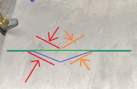
Basically by running two passes from 2 angles down the sheet I made groove/ditch.
Think of the green line as the sheet before shaping, the blue after shaping, this would be the profile looking from the "top" of the sheet.
The hammer/anvil is the red lines, with the arrows showing how they hit together, for the first pass and then the orange for the second pass.
IMG_8587 - Copy2.jpg

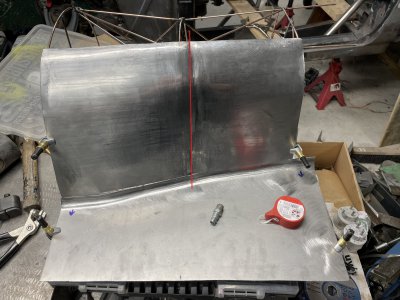
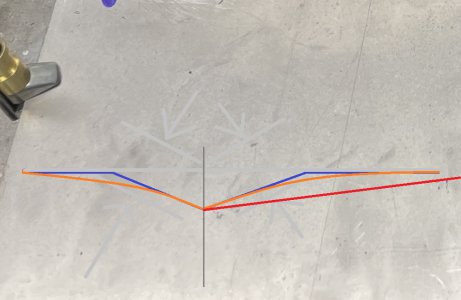
I like the left side but both sides combined makes it look too much like waist. What I want is a "bulbous" left half which then somewhat blends into a flatter right half. I think I would like to keep a "line" in the middle there but blend the right side of it much better.
In the photo I've already wheeled quite a bit on the edges of the groove to smooth them down, achieving roughly the orange profile in the second picture.
I think/hope I can shape the right side more like the red line by shrinking the edge down, after making the line straighter with the beadroller.
This would be easy with the shrink/stretcher but not sure if it has enough throatdepth, I could cut the sheet apart but I would like to keep welding to a minimum as it's messy and blending welds takes time.
Come to think of it, two custom wheels for the beadroller could clean this shape up and push the right side flat quite easily, need to see if I have any stock large enough.
IMG_8587.JPGIMG_8587 - Copy63.jpg
 
Last edited:
Thank you :)
I think the muscles/tendons are just overworked, symptoms of tennis elbow sounds a lot like what I'm experiencing on top of my hand going numb. Seems it's just one bodily issue to another ever since I got above the age of 30. :grin:
Giving it a week or so and trying to do a lot less heavy physical stuff for now before I start the whole carousel of getting a physio to look into it.

I was unusually motivated today and got quite a lot of work done(so much for taking it easy etc).
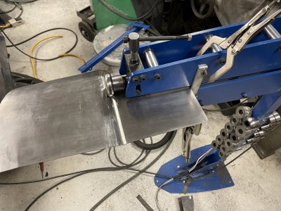
Clamped a endstop to the beadroller and rolled quite hard into the sheet to even out the line.
Seems a lot of these things you need to overdo because anything you do after will "take them out" again.
IMG_8595.JPG

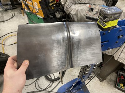
Here's just after beadrolling and then after using the english wheel to take off the sharp edge at the end of the radius.
I also added a "step" to the left, something clutch related is just behind there which is why the floor is a bit pearshaped, decided I might as well make it a feature instead of hiding it.
IMG_8597.JPGIMG_8599.JPG

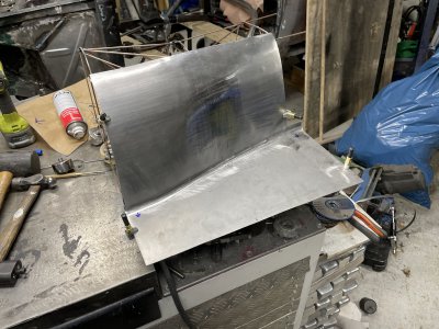
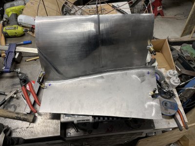
Fit up along the bottom is pretty good but everything is very uneven and it's not even remotely close to touching the buck at the top.
It's absolutely not critical that it's touching the buck, rather the opposite, if it leans too far in it will be too close to the gearbox etc ..
But I still want to do my best at making the shape I set out to do.
One thing I really struggle with is understanding if I need more shape/area or if I need to bend/twist things somehow.
IMG_8600.JPG

I did try twisting and bending this quite a bit back and forth until I ended up with everything "almost fitting" except this part where there's clearly way too much metal.
I did my best at shrinking this down with the shrinker/stretcher but it really doesn't like material this thick.
I think oxytorch and hot-shrinking would've been a better method but it's still on my wishlist.
IMG_8602.JPG

A lot of shrinking, hammering and beadrolling later... I've noticed this recurring thing where you try to change certain parts/shapes and it causes a chain of events so you keep chasing your tail to fix those.
I guess the 'best' way to sort that is to not make the wrong shape to start with. :grin:
Jokes aside, I think I should've made my wirebuck much more dense to better understand the shape I was trying to make, that would've showed me earlier just how much less metal I would need in the back.
Not gonna lie, quite proud of this right now despite it's flaws. :cool:
All the scratches on the right are from the shrinker and there's some places to fine tune but it's close enough for me, at this stage.
IMG_8604.JPGIMG_8603.JPG

Finally another shot at the buck.
It's now quite tight at the front and rear, definitely close enough to push it into place and tack things when it's time for that.
It's around 1cm away from the buck at the center "ring" with a little bit bigger gap just below that.
I'm going to call that good enough since I like how the shape looks and sorting that out "just because" will definitely not be worth it.
IMG_8606.JPG
 
Back
Top