Buying a new mill

I thought that I would post this video here as well. It will consolidate all my mill posts into one.

This video demonstrates the Z-axis handle I move to the front of the PM45.

[video=youtube;OcfJtyQAsjU]http://www.youtube.com/watch?feature=player_embedded&v=OcfJtyQAsjU[/video]

For those interesting in the full post you can find it HERE.

The drawings and a parts list can be found HERE.

Gary
 
I thought I would give you guys a heads up. The seals have started to leak on my PM45 and Matt sent me some replacements.

I will be going through the process this evening on replacing them, so look for it soon!

Gary
 
Good morning - I will be looking forward for that post as my PM-45 has started to leak also. At first it was leaking at the bottom of the face plate but tighten up the screws took care of that now it's leaking around the spindle.

Thanks,
Woodrow
 
Here's what I did to replace the spindle seals on my PM45-M.

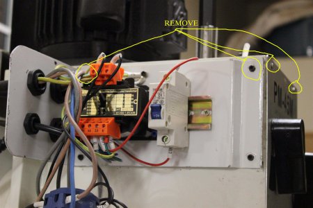
The first thing you need to do is to unplug your machine and THEN remove the electrical cover.

There are 4 screws you need to remove that are connected to the top cover of the mill.
See the picture below.
001 (Custom).JPG

Once that is done you will need to remove the 4 screws from the flange of the motor.
I had to use a ball end allen wrench to do this since the motor fins were in the way. Yours may be different.
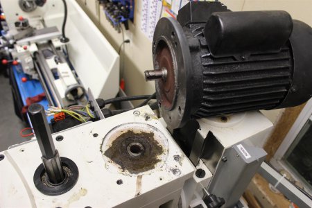
Once they are removed you need to lift the motor straight up. You may have to bang on the motor with your hand
to break it loose. Once you get it off you are rewarded with this view.

Note the key for the shaft stayed in the hole and not the motor shaft on mine.
Don't leave the motor balanced on the top of the column like in the photo. I did that just for the photo. It's VERY
easy to knock it off!
002 (Custom).JPG

Next you remove the 6 screws holding the cover on. They are all the same length to don't worry about
keeping track of which screw went in which hole.

There are dowels used to align the cover so you will need to lift it more or less straight up. I used a couple pieces
of bar stock that fit into the bolt holes. I put them in opposite corners and pushed the ends toward the center while lifting.
It takes a little wiggling and work but it does come off.

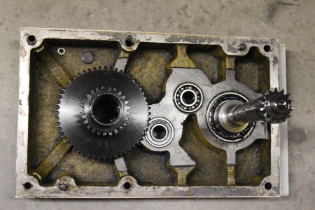
This is what the underside of the cover plate looks like.
003 (Custom).JPG

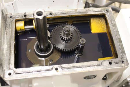
And this is what it looks like inside with some semi transparent oil.

The seals are pressed in at the point where the spline protrudes. The only time oil can even get to the seals
is when the head is rotated or when it's splashed while running.
004 (Custom).JPG

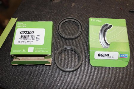
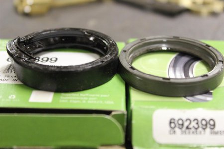
Here are the seals I received from Matt. The picture on the right shows a comparison between the new and old.
As you can see from the old seal I had to destroy it to remove it. I used a sharp chisel and hammer at two points
around the seal to cut it. This created enough room for me to give a pair of needle noses pliers enough grip to remove them.
There is another one under the first, so I did the same thing twice.
005 (Custom).JPG006 (Custom).JPG

Here's a closeup where you can see my new seals in place
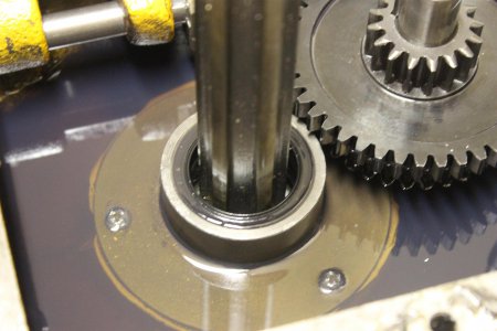
009 (Custom).JPG

While I was at it I siphoned out all the oil to replace it. I didn't find any metal chips or sand in there.
The shiny parts that look like metal filings are just where the casting was showing through the paint.
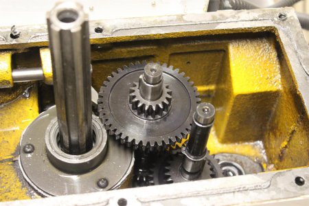
007 (Custom).JPG

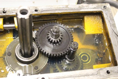
Then I filled it back up with some DTE medium oil and closed it up. I just used the reverse of the procedure I used to take it apart.
I did have one difficulty replacing the cover and that was getting the long shaft with the gear to line up. What I did was to once
again use a piece of round stock that just fit into the hole. This gave me the leverage I needed to line up and rotate the shaft to
position it properly.
008 (Custom).JPG

While I had it empty I removed the drain plug to see if I could identify the threads but to no avail.
I used a SAE and metric set of thread gauges but nothing matched. It's close to a 1/4" NPT.
I could actually start a 1/4" NPT fitting in the hole so I'm sure you could run a NPT tap in there
to open the hole.

The access it easy enough for the plug so I'm not going to worry about it.

All in all it took me about 1 1/2 hours. With this information you can probably do it faster.

I hope this helps someone.

Gary

001 (Custom).JPG 002 (Custom).JPG 003 (Custom).JPG 004 (Custom).JPG 005 (Custom).JPG 006 (Custom).JPG 007 (Custom).JPG 008 (Custom).JPG 009 (Custom).JPG
 
Hey Gary thanks... My seals are still holding up but, can give us a part number for them?


Ray
 
Ray, looks like a part # of 692399 on the box for the seal.


Gary,
How does the top cover seal? RTV?

This seal might seal all the time if the head was rotated to the side, so would the cover.

Without knowing anything, I would wonder if the leak could be coming from that seal bracket that is held down with 3 phillips screws. If it has RTV (looks that way in the picture) It might not have filled all the voids. Just a idea if the leak comes back.

The Threads for the Drain might be 1/4" BSPT if NPT sorta fits. BSPT is the same standard as JIS pipe BTW. BSPT is 19 threads per inch while NPT is 18tpi for the 1/4" size. The threads are also cut at a 55 degree angle instead of the US standard of 60 degrees

Alan,

The cover does seal with RTV.
When I saw that plate held with 3 screws I thought the same thing. If it starts to leak again it will be something I look at, but since it wasn't leaking from day one I don't think that was the problem. The RTV is evenly squeezed out around the edges.

I figured that the oil plug was BSP all along, but like I said I'm not going to worry too much about that. Now for my PM1236 lathe I will be doing something about it. Thanks!

Gary
 
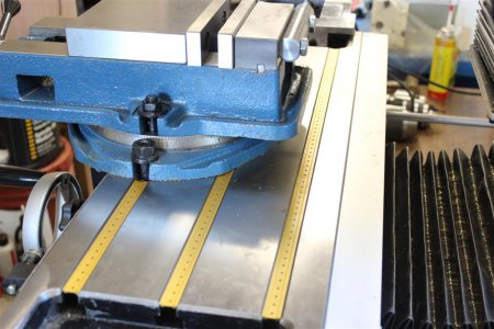
New T-Slot covers

Finally got some T-Slot covers in 14mm. About all you see around are for standard 5/8" slots for Bridgeport clones.

I saw then on ebay a while ago, but they didn't stock them and they said it took about 8 weeks to get them.

Recently I asked them about their stock and they said they had them. I don't know if they still have any but you can ask them yourself
if you are interested. HERE

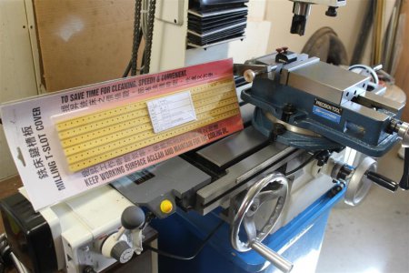
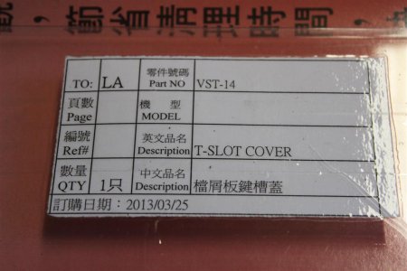
Anyway here they are. Your typical chinglish writing on the package.

IMG_2304.JPG

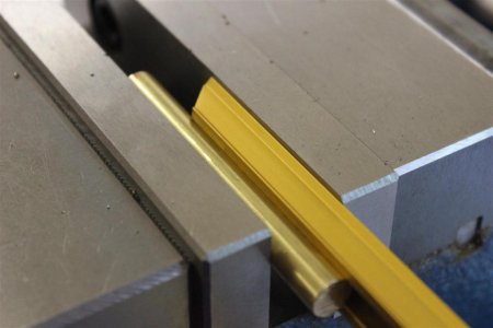
Now they fit the slot with no pressure at all. I didn't want them to slide around so I used a piece of 3/8" bar in the vise
to spread them for a snug fit. You only really need to do it on the ends.

IMG_2306.JPG

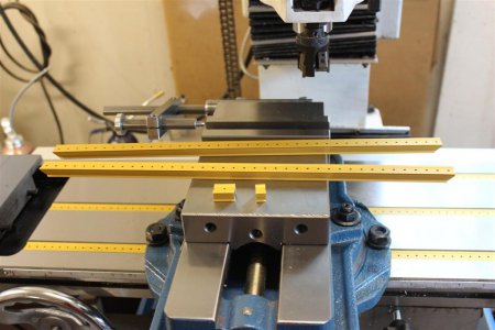
I filled two slots completely and the third to the T-Nuts holding the vise. It worked out pretty good.
I ended up with two extra pieces for future use and you can see the combined 1" of scrap.
Can't get much better than that.

They do have little holes in them for those using coolant.

IMG_2308.JPG

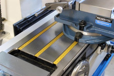
Here is a completed view from both ends of the table.

IMG_2309.JPG
IMG_2310.JPG

Maybe Matt would be interested in importing these for his mills. A real nice touch and won't cost that much.

IMG_2314.JPG

Gary

IMG_2304.JPG IMG_2306.JPG IMG_2308.JPG IMG_2309.JPG IMG_2310.JPG IMG_2314.JPG
 
That's a very nice looking mill. Iv'e ben looking at some used bridgeports and people think they are made of gold!! I might have to look at one of these instead.

This is the same problem that I have having, old tired machines that need a lot of work to get into any kind of usable condition and people want top money for them. Been looking for about 6 months now with no real luck, might have to bite the bullet and go with either the Rong Fu or IH 45 models. I'm a guy looking for a deal and I find it hard to part with my cash lol.
 
What model Homge vise is that? Couldn't be sure looking at their website!

Thanks


As promised here is the information on the vise.

View attachment 49608

First my search centered around a vise with an acme screw. It would be a lot more heavy duty and a show of quality. I looked at Shars, Enco and Grizzly. The all had regular 60° thread screws.

I talked to Matt at QMT and he said that the Homge vises had acme screws. To tell you the truth I still haven't see the acme screw. It's completely covered up with no exposure to chips at all.
Matt has been honest with me so far, so I will take his word for it.

Here are some pictures of the screw:
View attachment 49613 View attachment 49614
These pictures are with the vise completly open and closed. Even the end of the screw has a cap on it.

The next series of pictures were taken with a dedicated marco zoom lens hence the lack of depth of field.
They show where the jaws meet. The first pic you can barely see the line where they meet. The second and third picture show the vise slightly open and then even more so.
When closed you can't even feel that are two separate jaws.

View attachment 49609 View attachment 49610View attachment 49611

All in all a very well made and precise vise. Well with the money in my book.

Gary
 
Back
Top