Buying a new mill

They look good. Do they work good & how do you like them so far?

I used them all day yesterday and they work pretty good. No fumbling for that lever.

I may get a couple of 3 prongs knobs for the y-axis though. That I think would probably be more comfortable.

Gary
 
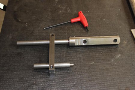
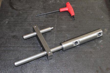
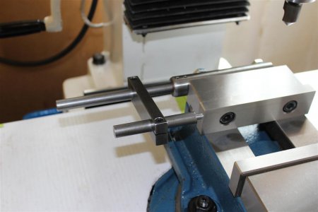
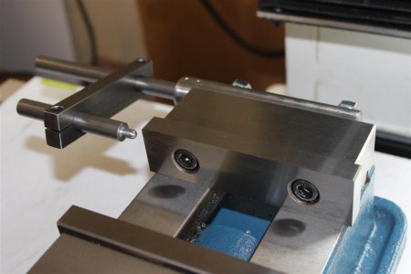
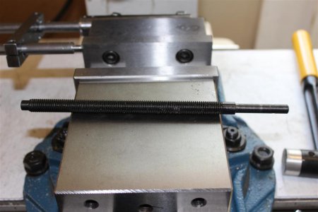
I made another little thing I will be needing today. A stop for my vise.

Not much but heavy duty!

PM45-M 1794.JPG PM45-M 1795.JPG


PM45-M 1796.JPG PM45-M 1798.JPG

Gary

PM45-M 1794.JPG PM45-M 1795.JPG PM45-M 1796.JPG PM45-M 1798.JPG
 
Excellent thread! Thanks for the pics and insight, I have been eye balling the PM45 and this is building up my confidence to go ahead and pull the trigger :)
 
I found one thing annoying so far. No big deal really, just annoying.

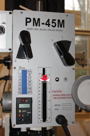
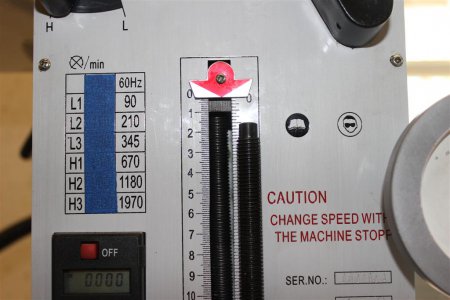
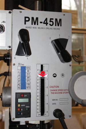
When looking at the speed chart on the front of the mill it has the speed settings for 50 and 60 hertz.

I don't know about you, but I will never use 50 Hz. So I just removed the distraction with a little masking tape.

Problem solved:

IMG_1808 (Large).JPG

Gary

IMG_1808 (Large).JPG
 
Another thing I though was kind of stupid for them to do when they assembled the mill is to install one part upside down.
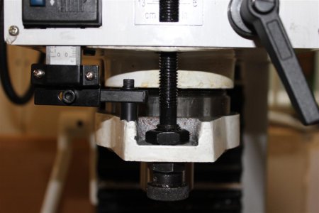
It's the clamping ring you see here at the bottom of the spindle column. In this picture it's right side up.

I assume they did it to give themselves a bigger bearing surface for the lower DRO mount. So I drilled and tapped a hole in the other side.
What is did was to make it harder to set the spindle depth with the knob you see at the bottom. With it upside down only
a small part of it protruded from the step in the clamp. Now it's fully exposed and a lot easier to use.

You might have noticed that I have the clamp as far down as it will go. This means I needed to add an spacer under the DRO mount.
I will show you why I did that at a later time. It's for something I will be adding to the machine.
IMG_1810 (Large).JPG


This created another problem. The combination of flipping the clamp and and moving it down, now means that the threaded stop rod
is too short to give me the full travel of the spindle. It was actually too short to start with, not allowing you to use the indicator correctly.
You can see in this picture that the stop indicator is about 3/4" from the top. If I move it up any farther it unscrews off the stop rod.
This means that I will need to either make a longer stop rod or just add an extension piece at the bottom where it's not threaded.
The latter will be the simple way so I will do that.

I have a few more additions that will be adding to the mill and hopefully everything will be complete, making it an even more functional machine.

Gary

IMG_1808 (Large).JPG

IMG_1810 (Large).JPG IMG_1808 (Large).JPG
 
Last post I told you the problem with the stop rod being too short after I flipped the clamping collar (for the lack of a better term) and lowered it.

In my last Enco order I got a piece of 12mm threaded rod.

I used it today to make a longer one like the one in the picture here:

IMG_1850 (Large).JPG

With it installed I now have full travel and use of the depth stop. Actually there is even more range than it came with.
Here you can see the shorter one next to the new one installed.

IMG_1851 (Large).JPG

Now there are just two more improvements I will be making to the mill so stay tuned.

Gary

IMG_1851 (Large).JPG IMG_1850 (Large).JPG
 
I did have a hard time getting the mill off the pallet since I didn't have the room for my hoist to straddle the pallet. I went ahead and lifted the mill at an angle and as the weight in the pallet decreased I could slide it closer to the lift point. I got it so light that only one corner was touching and pivoted it on the corner and it was air born.

Lifting it high enough to get on the base was no problem. Very anti-climatic. Then I had to move the old one.

Gary

Hi Gary,

I'm evaluating whether this mill will fit in my basement. The ceiling in my shop is the main floor of the house. The floor joists above are 7'5" from the concrete floor of the shop, and the joists are another 7" or so.

I'm reasonably certain that the assembled machine isn't too tall, but I'm going to have to hoist it high enough to get it on top of the base. I checked on the Quality Machine shop and they don't have a height for the assembled machine. Could you spare me a moment of your time and measure that?

I'm thinking that a wooden gantry with 4x4" columns, doubled 2"x8" header (need to check this) and secured to the overhead floor joists should be adequate to support a winch, but there's only so much vertical space to work with.

Walt
 
Hello Walt,

It's 68" total. This is with a cast iron base so I'm not sure if the steel base is the same. I can't see it being more than an inch or so different.

When the head is up all the way the motor stick above the 68".

Hope this helps,

Gary
 
Hello Walt,

It's 68" total. This is with a cast iron base so I'm not sure if the steel base is the same. I can't see it being more than an inch or so different.

When the head is up all the way the motor stick above the 68".

Hope this helps,

Gary

I took measurements for someone else previously and mine (with the steel base) is 68" also. Mine is 74.5 to the top of the column & my riser is adding 6.5". With the head raised to the top I get about 89" to the top of the motor so without the base it's 82.5"
 
Gary-

I don't have this machine, but still find myself reading the whole thread :)
So thanks for being one of those folks who bother to helpfully share so much on here. Not too many machinists around, so we gotta help each other.

I am thrilled for you with your purchases recently! I was looking at a mill like yours once, but went another direction. I look forward to your updates.

And I have to say, damn nice vice!! I can't believe the tolerance on those jaws!! I have only heard great things about Matt, being a pretty straight up guy.


Bernie
 
Back
Top