- Joined
- Aug 31, 2013
- Messages
- 54
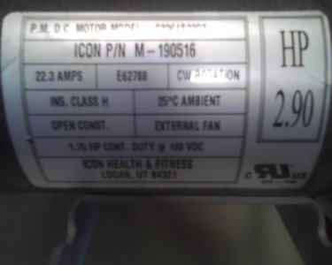
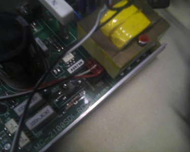
I would like to use this motor and control board on my 1928 9" Southbend Lathe.


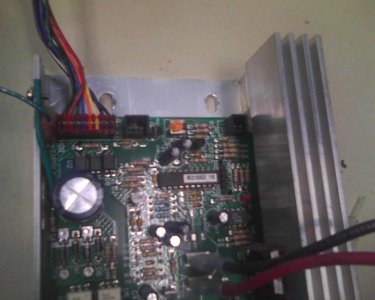
I would like to know where to attach a Potentiometer. Or if it is just that simple.
Here's what I need explained....
HD2- This eight wire connection attaches the controller to the console. Each wire carries the following voltage signal:
BLACK- (Two wires) These are the ground wires for the console. All other voltages taken on the 8-wire harness are in
reference to either of these wires. Note: On the MC-2100SDI, the second Black wire (the one next to Violet) carries
a very small pulsing voltage the console monitors to count the number of steps taken by the user.
RED- This wire supplies the console with 9 VDC.
GREEN- This wire brings the speed sensor signal to the console. This is a pulsing 0, 5 VDC signal as the treadmill is
running. When the treadmill is at rest, this voltage may measure either 0 VDC or 5 VDC.
BLUE- This wire carries the square wave speed control signal from the console to the power board. The duty cycle of
this 5 VDC signal is used to set the speed of the treadmill. At the maximum duty cycle of 85% (meaning the 5 VDC
is being sent 85% of the time and not being sent 15% of the time), approximately 4 VDC can be measured. At lower
speeds, a lower voltage will be measured. NOTE: Many digital multimeters have difficulty measuring this square
wave signal. They may only show a maximum of 1.5 VDC whenthe treadmill is set to its maximum speed. What is
important to see in this instance is that the voltage goes up as the treadmill speed is increased.
ORANGE- This wire carries a 3.5–5 VDC signal to the power board to cause the power board to send 120 VAC to the
incline motor to increase the incline setting of the treadmill.This voltage should only be present when the incline is
being increased.
YELLOW- This wire carries a 3.5–5 VDC signal to the powerboard to cause the power board to send 120 VAC to the
incline motor to decrease the incline setting of the treadmill.This voltage should only be present when the incline is
being decreased.
VIOLET- This wire carries the incline sensor signal to the console This is a pulsing 0, 5 VDC signal as the incline is
moving. When the incline is at rest, this voltage may measure either 0 VDC or 5 VDC.
Thanks,
Rick


