MachTach Build

Blackjackjacques

Registered
Registered
Joined
May 20, 2017
Messages
162
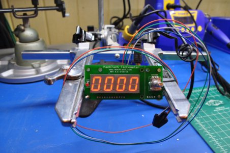
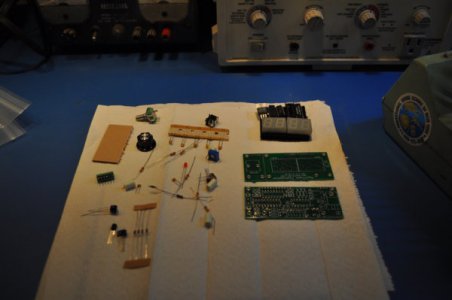
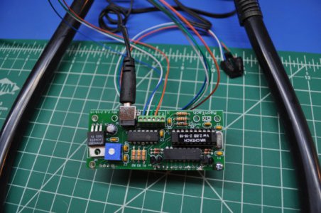
Ok - got some free time and wanted to at least commence tackling set up of my RF45, which includes DRO install, tramming, and building of the MachTach tachometer product. It has been sitting in its half-opened yellow envelope for a few months now, so now it is at least assembled and soldered together and has passed the preliminary vendor tests. It went together pretty easy, however, it is smaller than I prefer. I was pretty impressed with the supplied plastic case that was constructed on a 3D printer. This is my first application where I had a chance to fondle a 3D printer product, and it much beefier and dimensioned than I expected. My next step will, of course, be to attach to the machine, but I think I will so that simultaneously with the DRO install. Has anyone built and/or used this MachTach product?
DSC_0396.jpg

DSC_0400.jpg

DSC_0403.jpg
 
I built one in a serpac enclosure. It worked fine when I test drove it on a desk fan. Looks good and took a minimal of tools. For me it was also a good excuse to fleabay an awesome WD1 weller soldering station,the one nice tool I used.
 
I built two, one a few years back for my lathe and one recently for my mill with the 3D printed case. I was impressed with the case as well. I used the magnetic induction sensor and with that there is a small 3D printed case, that is interesting with the internal passage printed perfectly for what it needs to do.

It is a high quality kit. I get what you mean with it sitting in an envelope until I got around to soldering it all together..

You can buy a cheap tachometer but not with the SFM function. Push the button, dial your diameter, lathe stock or end mill and get surface speed.

The place that sells them is very accommodating. The instructions let you know how to wire one unit up to two machines if you have two machines close to each other. Can order with whatever sensor you want.

Can mount it inside the case of your tool if there is room.

The little plastic colored window needs to be trimmed down to fit the cut out in the 3D printed case. I did that easily by clamping the red plastic in a vise and carefully filing the edge down to size. Thought about cutting it on my mill but I worried about cracking it.
 
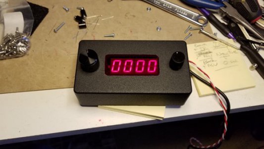
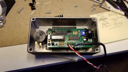
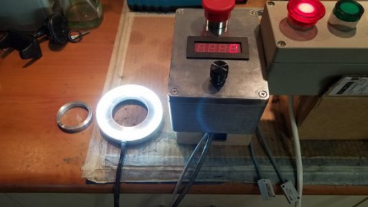
Built a few of the MachTachs, although I prefer to mount them in Hammond diecast enclosures. Not as easy to do vs. the 3D case. I use the SFM on larger diameter work on my lathe, helpful to tell you if you are ball park SFM. Most recent version does metric. More recently I have also been adding a precision 3 turn speed pot in my tach enclosures. Much better quality pot and I do not need to take up a larger 22mm hole. One minor issue I have had with the MachTachs is they require a 9V power source, typically most low voltage control systems are 12 or 24VDC. Some systems I needed yet another step down converter or add a heat sink to the regulator if there is room (you can see below that the heat sink needed to be modified to fit the case). I also used a more standard round threaded hall sensor on lathes if you have the room. In one case the tach was sensitive to VFD electrical noise, but I managed to work that one out. The documentation in the manual is very clear, also availability of different sensors makes this tach a bit more adaptable. Had a recent discussion with the builder and some suggestions, nice person and listens to comments.

Mactach RPM Display and Hall Sensor.jpg
20180130_171300.jpg
20180130_171328.jpg
 
I built one in a serpac enclosure. It worked fine when I test drove it on a desk fan. Looks good and took a minimal of tools. For me it was also a good excuse to fleabay an awesome WD1 weller soldering station,the one nice tool I used.

Aye - the Weller WD1 is a slick tool. I started with an old Weller TC 201 and then slid over to my Hakko FX 888 and batted cleanup with my Hakko FR 810B hot air unit. My eyes are not what they used to be and last night I needed the microscope more than usual. But it cleaned up nicely and worked the first time powered up.
 
I built two, one a few years back for my lathe and one recently for my mill with the 3D printed case. I was impressed with the case as well. I used the magnetic induction sensor and with that there is a small 3D printed case, that is interesting with the internal passage printed perfectly for what it needs to do.

It is a high quality kit. I get what you mean with it sitting in an envelope until I got around to soldering it all together..

You can buy a cheap tachometer but not with the SFM function. Push the button, dial your diameter, lathe stock or end mill and get surface speed.

The place that sells them is very accommodating. The instructions let you know how to wire one unit up to two machines if you have two machines close to each other. Can order with whatever sensor you want.

Can mount it inside the case of your tool if there is room.

The little plastic colored window needs to be trimmed down to fit the cut out in the 3D printed case. I did that easily by clamping the red plastic in a vise and carefully filing the edge down to size. Thought about cutting it on my mill but I worried about cracking it.

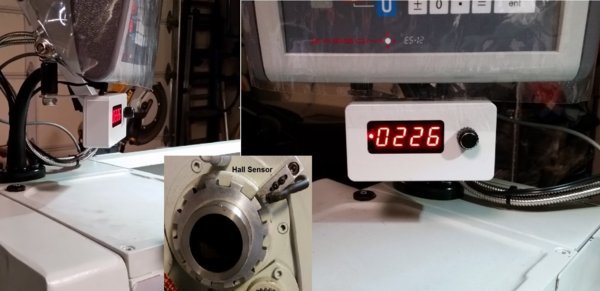
I'm glad to hear there are others out there who relate to half-opened envelope projects. I have a few more envelopes yet. I have the standard optical sensor shipped with the unit, but I purchased the hall effect sensor along with this killer neodymium magnets, but I'm wondering if I should instead go with the variable reluctance sensor instead to detect gear teeth. My preliminary plan is to access the geared drive behind the front access plate. From that point, I can go either with the hall effect unit or the var reluctance, but I debating with myself if it is easier to just use the var rel since I do not need to space and install magnets, etc. The display unit itself will be installed external to the machine but flush mounted to the front plate (I think)
 
Built a few of the MachTachs, although I prefer to mount them in Hammond diecast enclosures. Not as easy to do vs. the 3D case. I use the SFM on larger diameter work on my lathe, helpful to tell you if you are ball park SFM. Most recent version does metric. More recently I have also been adding a precision 3 turn speed pot in my tach enclosures. Much better quality pot and I do not need to take up a larger 22mm hole. One minor issue I have had with the MachTachs is they require a 9V power source, typically most low voltage control systems are 12 or 24VDC. Some systems I needed yet another step down converter or add a heat sink to the regulator if there is room (you can see below that the heat sink needed to be modified to fit the case). I also used a more standard round threaded hall sensor on lathes if you have the room. In one case the tach was sensitive to VFD electrical noise, but I managed to work that one out. The documentation in the manual is very clear, also availability of different sensors makes this tach a bit more adaptable. Had a recent discussion with the builder and some suggestions, nice person and listens to comments.

View attachment 256638
View attachment 256639
View attachment 256640


Nice slick black. I was considering using a Bud Cu-124 case similar to your Hammond, but the Serpac plastic 3D printer case was so nice, I put the Bud box back into inventory. But if I experience a noise interference issue as you described in your case, I may have to go the metal enclosure route -- we'll see. I see the speed pot you added to your unit - what does it do? I have not mounted a heat sink to the 3-terminal regulator yet. I have low profile TO-220 heat sinks that go taller rather than wider, and need to figure out which one to include. A note on regulators: on Ebay, there are a ton of China smt buck boost regulator packages that essentially go from any voltage to any voltage, for about 80 cents apiece. You can easily interface a 9V to 12V, 18V, 24V, or even 5 and 3.3 V with a device about the footprint of a postage stamp.
 
The electrical noise issue was not the enclosure, but the shielded cable between the hall sensor and the MachTach. Convention would be to ground the shield at the source (not both ends), but any grounding of the shield (either end or at both ends) made the MachTach go wild. So if you use shielded cable, my recommendation is float it on both ends. Grounding is always one of those funny things, doesn't always work the way it is suppose to.

I would go with the hall sensor, you also only need a single magnetic to KISS. The IC hall sensor provided with the kit is a bit fragile, I used it on my lathe but wouldn't want to use it again if possible. You can get the cylindrical threaded type, NPN in 8 or 12 mm diameters. You connect the hall sensor brown power to wire to +IR, the blue negative to -RCV, and the black switched sensor line to +RCV. Works very nicely and no need for a pull down resistor.
Examples of sensors:
NJK-5001C
LJ12A3-4-Z/BX

Gear tooth sensor can be a bit more temperamental, you need the assembly he provides with the two capacitors in order for it to work correctly. At least he has it as an option. One problem on mills with a back gear, is you cannot take the tach off of the drive head, you need to pull the tack signal off of the spindle so need a very compact pickup assembly. One place where the small hall sensor is more desirable. On my mill which came with a factory tach, it uses an output from the VFD for speed and they also have a back gear sensor which rescales the tach range when in back gear. I recently build two integrated Halo Light and tach sensor for some PM 949 mills that where 1/4 thick and slid up on the mill ram. They required a very small hall sensor, it was very temperamental to magnetic flux.

20171214_100942.jpg
 
Would there be any problem if I were to glue a strong magnet on the back of the 3D printed half size case? If I could do that there is a place to stick it up but also be able to move it easily.

Would a strong magnet bother the electronics?
 
Back
Top