- Joined
- Mar 20, 2014
- Messages
- 418
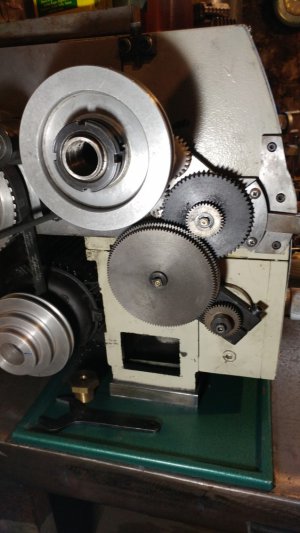
72 & 24 tooth HTD M3 x 15mm, so the same 3:1 ratio as James. Seemed to be the easiest way forward as he’s proven that it works with the hybrid stepper / servo

")
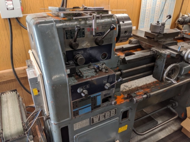
just saw your Youtube torque test Jon, Wow , the forces involved on a leadscrew = vicious!! no wonder 1/2 nut backlash eventuatesMy shop looks tidy only because of careful framing. It's a wreck, and I barely have room to turn around, which is why I planned to build a detached shop this year about three times the size, but it's looking more like a spring thing all the time.
I'm sticking with the "programmable gearbox" concept for the foreseeable future. No CNC for me, thank you. I still might look at a micro with quadrature decoding at some point. I have no need for floating point the way I'm doing things. I have interpolation error but no accumulation of rounding error, and I can stop at a limit on the same count all day long, better than I can measure with a tenth indicator.
I gave very serious consideration to the Clearpath servos, but cheaped out. The "hiccups" I'm seeing are momentary stalls on heavy cuts that aren't quite big enough to cause my microstepper driver to error out. I think I can fix it by increasing the gear ratio between the motor and lead screw. I'm currently running 4:1, but have ordered timing pulleys and belts that will allow me to test 5-, 6- and 8-to-one. If that's still not enough, I might start thinking about Clearpath again. They have one that ought to be a drop-in, and would double the torque. I just balk at the price tag.
I've been reasonably happy with my TouchDRO setups. I'm using Shars scales with added decoupling caps in the heads to make them more stable. I have the cross feed scale on the lathe mounted above the screw, covered and completely out of the way, and I would have a hell of a time doing that with any other kind of scale. About the only possibility would be a DroPros magnetic scale. I wish Yuriy would get fired up and fix a few things, but he seems to have moved on.
Take care.
Two hours, and I was the first to lose out. Went to Ebay and it said he had two left. Ordered two and it said, not enough in stock. Ordered one, hit Buy, and "sorry, all out." I think I'm one of the few who actually has the entire thing running; I have the discrete boards but I just like how his board cleans up the wiring. I'm pushing forward on getting it entirely finished such that his board is the only holdup....the first batch of 100 sold out in about 4 hours...
Two hours
I ordered a board yesterday and had a message from Paypal this morning to say it's been shipped.Two hours, and I was the first to lose out. Went to Ebay and it said he had two left. Ordered two and it said, not enough in stock. Ordered one, hit Buy, and "sorry, all out." I think I'm one of the few who actually has the entire thing running; I have the discrete boards but I just like how his board cleans up the wiring. I'm pushing forward on getting it entirely finished such that his board is the only holdup.
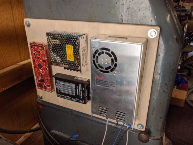
To be honest, I'm not quite sure why I decided to put the assembly on the lathe itself instead of the wall. I guess I just like knowing that if I have to move the lathe, there aren't any "appendages" other than the power cord. And yes, there will be a cover over the assembly, because with 0.020 pitch on a couple of the ICs on the development board, it wouldn't take much for a chip to short out things...
Separately, I have no idea if the little belt I'm using will be sufficient for driving the carriage, because there's probably a dozen variables in figuring out the torque. Speed of cut, depth of cut, cutter type, cutter sharpness, material being cut, spindle speed, gear reduction of lead screw, gear reduction of QCGB, gear reduction of belt pullies, torque capacity of the servo motor, and probably more I'm forgetting.
I ordered a board yesterday and had a message from Paypal this morning to say it's been shipped.
just saw your Youtube torque test Jon, Wow , the forces involved on a leadscrew = vicious!! no wonder 1/2 nut backlash eventuates
Jon Bryan
8 hours ago, youtube.
"Down the rabbit hole I go. I'm trying to score a force gauge and actually measure it. Rough T = KDP calculation gives me a number between 550 and 1100 pounds of force applied to the carriage depending on the friction loss. I can tell you that even before I geared it down I could push on it my hardest without slowing it down, and I weigh about 270, so I'm inclined to believe the rough calculation. Gives you an appreciation for the kind of cutting forces that are involved when cutting an 8tpi thread."
So,
Not being a mech engineer or F & T, i need clarification here: T = KDP?? (so something related to diametral pitch?)..
(wikipedia = Kurdistan Democratic Party, lol.) its ok, i'll dig for it..
Why not simply do lots of light cuts, (- nicer job? )
to ease up the forces on the 1/2 nuts, leadscrew, bearings etc? After all U don't cut an 8 TPI thread very oft, do you?
Well i don't anyway, & if needed, i wouldn't be in too great a hurry.
- i Just got an answer from Clough42 re his ELS, man is he gunna be busy, new breakout boards for his TI piccolo sold out in hrs!!
I don't quite get the rush, after all he said the board isn't crucial to the project, but nice to have pretty lights to indicate activity, i suppose.
James advised me re your latest Vid., Thanks to him, & certainly, thanks to you - the torque wrench was a profoundly simple way to indicate static stepper torque or holding force. [some drives can be set to 50% idle current, or standstill current ('Leadshine' terminology!) reducing heat build up in the stepper windings].
Q: U seem to be operating a closed loop stepper, it cant be a system reaction to the spindle encoder movement, as there's no direct link from the spindle cog & fwd/rev idlers to the gearbox input anymore, being the point of the ELS!
i mean, i get the holding control of the stepper drive, resisting forced steps, but after 1 step overcome mechanically, i would have thought it would lock into that new step, not go back as depicted, which seemed to be a heap of steps. (unless its a closed loop). Puzzled.
Also, about those idlers & the encoder drive train, wouldn't there be too much backlash / slop between spindle motion & the encoder rotation, given they are only spur gears? I get the need to sense fwd/rev. but that can be done direct off the spindle, with virtually no missed pulse edges.
Maybe i missed something there, too
I do hope U find that suitable force gauge..
cheers, Qtron.
P.S. A blank Mega awaits, Tongue hanging out for that magic code now Sir Jon!!