1022 CNC Receiver Project

jbolt

Active User
H-M Supporter Gold Member
Joined
Dec 3, 2013
Messages
1,849
As a CNC learning project I decided to do a custom 1022 receiver. I figured I would post a thread about the good, bad and ugly as I go through the process.

I am using Solidworks for the CAD and a free add-on CAM program called HSM Express. HSM Express is only 2.5D. I'm not endorsing one program over another. As a mentor for a high school robotics team, we use Solidworks for our CAD and I get a yearly licence for free. Using the free version of HSM was a no brainer. What I do like about HSM Express is that it is embedded in the CAD program.

For many years I used AutoCad to make 2D drawings for manual machining. When I first had the opportunity to use Solidworks a few years ago I was sold on the idea of modeling pats is 3D. I'm still very much a novice to Solidworks but projects like these really help build your skills.

I have the CAD completed and the CAM tool paths generated for the main part of the receiver.

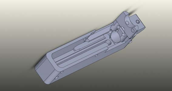
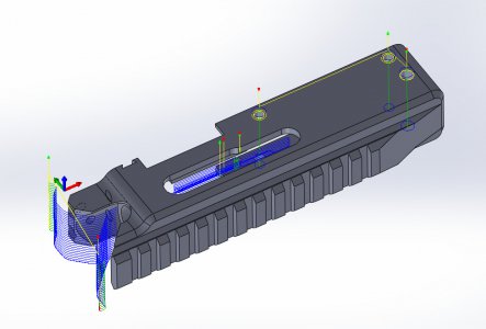
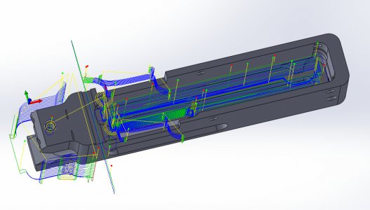
Here is a capture of the CAD model.
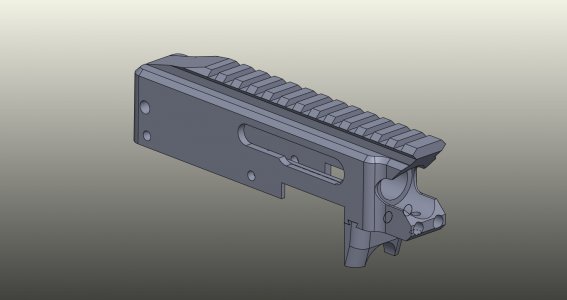
1022JCS.jpg1022JCS002.jpg

If look at the lower lug of the receiver you will see a dovetail joint. The OEM 1022 receiver is an aluminum casting which unfortunately does not simply translate to machining. Doing the receiver in two parts simplifies a number of operations. I will get into more detail about this when I do that operation.

To be continued.......

Jay

1022JCS.jpg 1022JCS002.jpg
 
On the main receiver body model there are 41 different machining operations. I broke these up into six separate jobs with each job representing a different face of the part. This is necessary because each face requires a work coordinate based on its orientation for machining.

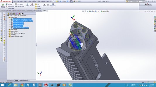
The first job is the front end of the receiver, I chose to do this first because the main pocket of the receiver is deep and this will help with chip evacuation during those operations. The screen capture below shows the jobs and operations. The job 1 operations are highlighted which shows the tool paths on the part.

Screen Job1.jpg

A really great feature is the CAM simulation. The first video is with the stock to be removed shown and the second is without.

[video=youtube;KtzM3Cfk1Ro]https://www.youtube.com/watch?v=KtzM3Cfk1Ro[/video]

[video=youtube;CDGBbkoFVEI]https://www.youtube.com/watch?v=CDGBbkoFVEI[/video]

Jay

Screen Job1.jpg
 
Wow, that's a pretty ambitious project. Nice work on the CAD model, I hope it comes out as good in real life.

"*** Xpress" is where it's at for 2.5D. It's better than any of the expensive ones I've used.
 
Thanks Andy. I really like *** but it does do some odd tool paths sometimes.


I'm a bit behind on posting progress due to back problems so I will try and catch up.


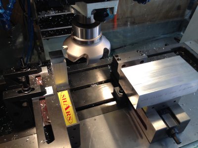
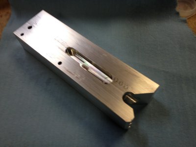
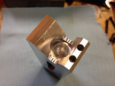
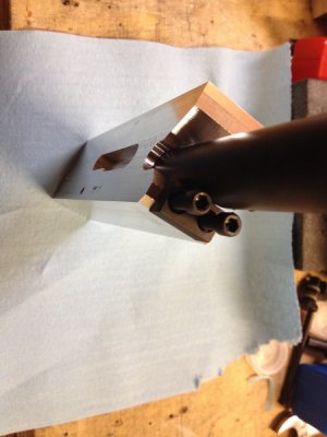
Here is my setup. I setup two 4" vises, one on its side to do the end operations and a second setup normally to do the top, bottom and side operations. All four material blanks were sized to the same length. Each vise is setup in Mach3 with its own offset so I don't have to re-zero each work session.

20140621_001.jpg

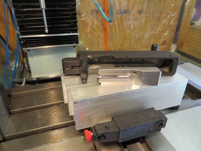
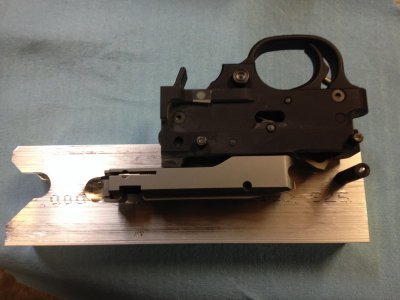
Here are the blanks ready to mill. On top is a stock receiver and a KIDD after market bolt.

20140629_005.JPG

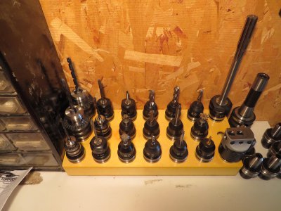
And here is the tooling set up in TTS tool holders. So far to run all the ops I have 21 different tools, 26 tool changes and 41 operations.

20140629_002.JPG20140629_003.JPG20140629_004.JPG

20140621_001.jpg 20140629_005.JPG 20140629_002.JPG 20140629_003.JPG 20140629_004.JPG
 
Okay this is the last bit about the setup before getting to the machining.

I'm not real good at explaining things sometimes so hopefully this will make sense.

For those who have not used work and tool offsets, in Mach3 on the offsets page you can set individual work offsets for your holding fixtures, vises in my case, and tool offsets if you are using repeatable too holders. There are 4 presettable offsets on the offset page, G56 through G59.

For my first operation I am machining the barrel end of the receiver in the left vise and I will use G55 for the work offset.

The machine is referenced to the home positions. Your home switches need to be repeatable for this to work. The proximity switches I'm using will repeat to (+-) 0.0005" which is good enough for what I'm doing. I'm still chasing some backlash in the ball screws so no point to try and make that any better until I that is resolved.

Once the x,y,z axis are homed then the holding fixture or part is zeroed and saved.

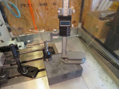
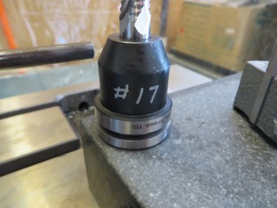
For the tooling I am using the Tormach tooling system holders. The holders are referenced off the face of the spindle and are held in a modified 3/4" R8 collet. Once a tool is setup it will always repeat to the same position so the tool can be removed and put back without having to reset the z each time. In the previous photo I show a tool being measured. Each tool is assigned a number, the height is measured and entered into the tool offset table in mach3.

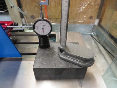
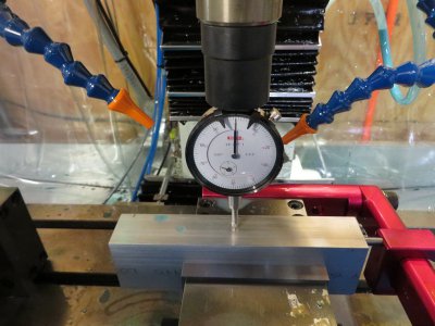
To make this all work you need a master tool or gauge block to reference the spindle face. I use a dial indicator in a special TTS holder. The dial is locked in place where it is easy to read when in the machine. With the plunger depressed 0.100" the offset from the face of the spindle is measured with a height guage. This now becomes the z offset. In my case the offset is 6.417"

Here is the master tool being measured.

20140719_001.JPG

and the z offset being set to the top of the part.

20140719_002.JPG

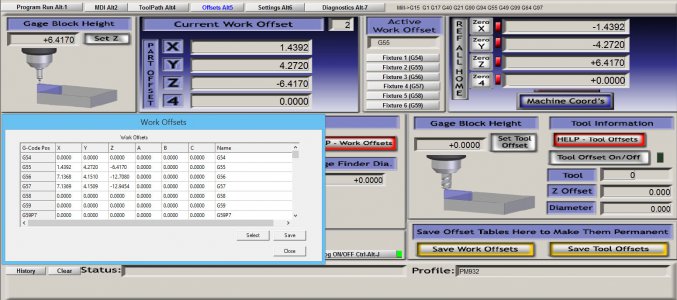
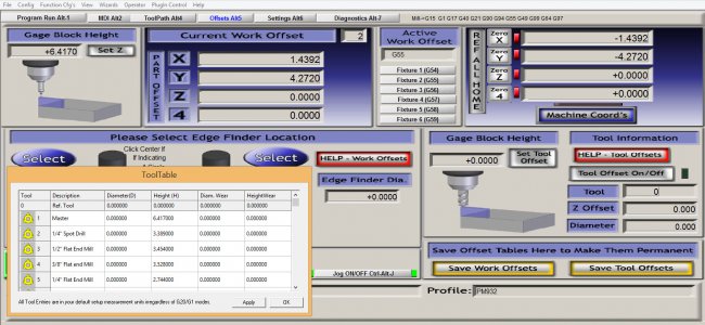
In the first screen capture the "Active Work Offset" is set to G55, the z offset is entered where it says "Gauge Block Height" and in the "Tool Information" the tool must be set to tool zero (0). The tool offset is 0.000" and the z position above (face of spindle) is +6.417" above the work piece. In the lower corner I left the fixture offset table open so you can see the z offset is set to 6.417 for the G55 line.

Offset Capture 1.jpg

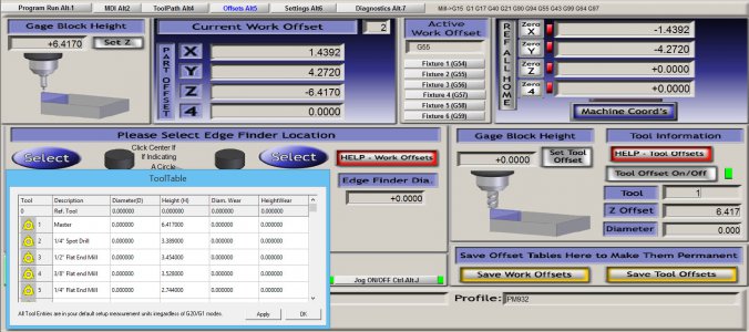
In the second capture I have switched to tool #1 which I have stored in the tool table as the master tool. Notice the green tool offset LED is now on, the tool offset now says 6.417 and the z position above (tip of master tool) is 0.000" to the work piece. In the lower left corner I left the tool table open so you can see how the tool height offsets are stored.

Offset Capture 2.jpg

In the g-code, at the beginning of the program, the work offset will be set with a (G5x) reference to the Mach 3 fixture offset table. Each tool is referenced by a number corresponding to the tool setup in the Mach3 tool table. Mach3 will read the tool number assignment (Tx) and reference the tool height offset from the table (Hx).

So to put it all together, with the work and tool offsets pre-programmed I can start and stop machining sessions without having to reset the work and tool zeros each tme.

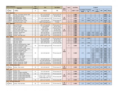
Because I have many different work position offsets, tools and tool changes for this project I made a spread sheet to keep track of it. Memory isn't what it used to be.

1022JCS CAM Ops.jpg

Clear as mud?

Jay

- - - Updated - - -

Okay now for some actual machining photos.

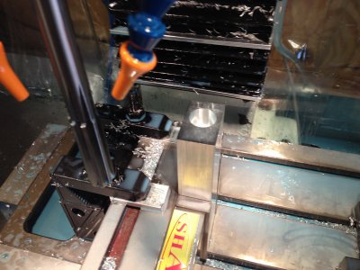
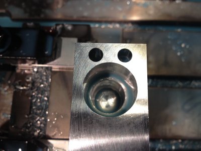
This is the fist operation completed. Drill relief and tap holes for the barrel retainer, rough mill the barrel recess and pocket, finish mill the barrel recess and finish ream the barrel pocket. Machining time about 7 minutes with 5 tool changes.

20140702_001.jpg20140702_002.jpg

20140719_001.JPG 20140719_002.JPG Offset Capture 1.jpg Offset Capture 1.jpg Offset Capture 2.jpg 1022JCS CAM Ops.jpg 20140702_001.jpg 20140702_002.jpg
 
This is job 2, the trigger frame mount holes (drill and ream), bolt stop hole (drill and ream), ejection port and front contour. 7 operation with 7 tool changes.

CAM tool paths

Job2 CAM Ops.jpg

Finished operations

20140704_002.jpg20140704_003.jpg

Test fit barrel and trigger frame holes

20140704_001.jpg20140704_004.jpg

I ran into my fist problem with the barrel recess being 0.005"too deep to the retainer lug. I made a mistake in the CAD model so this will be fixed for the remaining parts. I'm considering the first receiver to be a test/setup part as I go through the learning process where I can make mistakes and learn how to improve my CAM operations.

Jay

Job2 CAM Ops.jpg 20140704_002.jpg 20140704_003.jpg 20140704_001.jpg 20140704_004.jpg
 
Very nice project. The progress looks good so far. I've seen these receivers machined from brass and steel as well, and even machined manually. I would like to see some details of your mill as well (in the proper section of course).

Definitely following this one.
 
Video of the finish passes on the front contour. I'm not real pleased with the finish. I used an extended length end mill for this op due to dropping something on the shorter one.

[video=youtube;QgaKwoNlRVU]https://www.youtube.com/watch?v=QgaKwoNlRVU[/video]
 
Very nice project. The progress looks good so far. I've seen these receivers machined from brass and steel as well, and even machined manually. I would like to see some details of your mill as well (in the proper section of course).

Definitely following this one.

Thanks Rick. Machine build thread is here

Jay
 
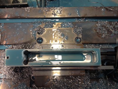
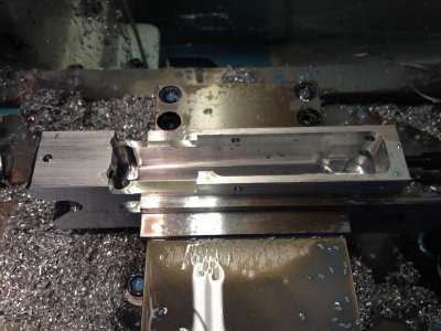
Machining the bottom pocket and side contours. 18 operations, 10 tool changes.

Tool paths.

Job 3 CAM ops.jpg


Because the OEM receiver is a casting the front area of the pocket has square inside corners. To create the necessary clearances for the bolt I drilled / milled a 3/8" hole at each corner.

he main pocket was roughed out using a 1/2 roughing cutter. In the 30 years I have done manual machining I have never used a roughing end mill. These things are awesome.

Video of the end of the roughing passes at 35 ipm. The slowdowns are when it ramps to the next level. I need to work on speeding this up.

[video=youtube;U-YDHD8WzMc]https://www.youtube.com/watch?v=U-YDHD8WzMc[/video]

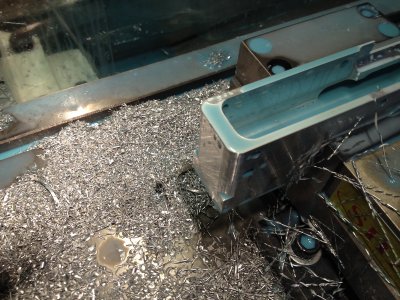
20140711_001.jpg20140711_002.jpg

Part was turned around in vise to do the rear contours.

20140711_003.jpg

Job 3 CAM ops.jpg 20140711_001.jpg 20140711_002.jpg 20140711_003.jpg
 
Back
Top