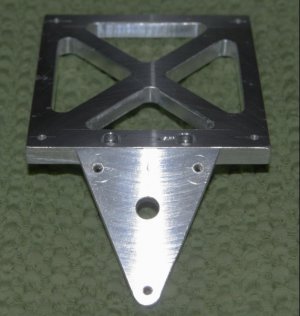
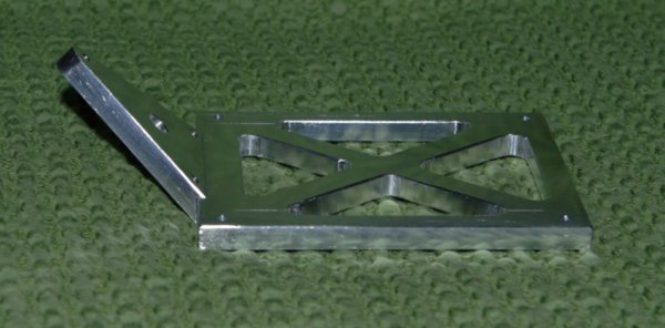
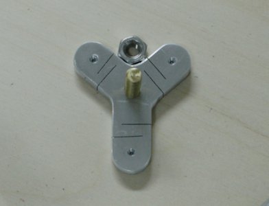
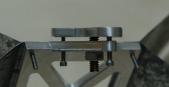
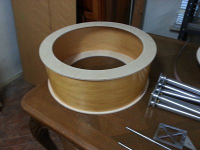
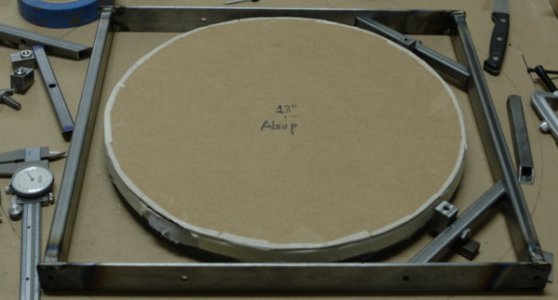
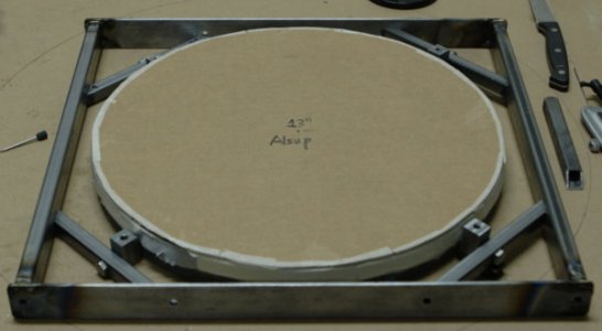
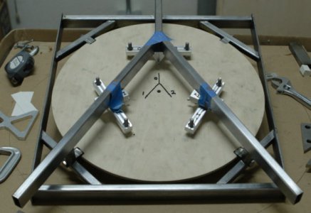
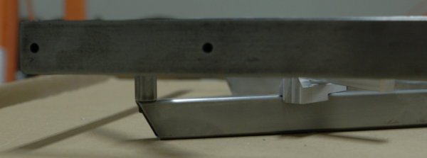
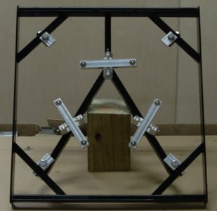
Today, I got a mirror cell support plate <jig> made.
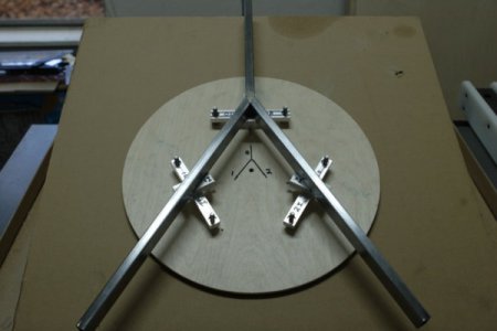
This support plate has 6 accurately positioned accurate diameter and height stand-offs to hold the
mirror beams in <near> perfect position so that the beam pivot supports can be attached to the
mirror cell frame. As machined, the tolerance on the positioning of any given point at the end of the
beam is on the order of 0.002".
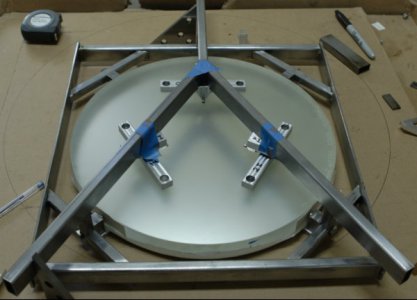
The Blue tape is just to hold the beam pivot supports in line so the mirror frame (Y) can be positioned.
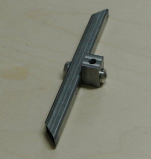
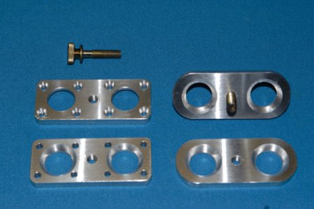
I was intending to use the brackets shown above and using a Muggy-Weld product to solder aluminum
to steel. Ultimately I could not figure out how to make sure that the two axles from each side were
sufficiently co-axial that I made different brackets (see 2 paragraphs later.)
This was the third try at making such a jig. The previous ones failed in the accuracy department and in
the usability department.
Basically over the last 3 weeks I have tried a number of ways to mount my 6-point cell beams to the Y-frame
such that the points at the ends of the beams are at exactly the right positions (within 0.003"). In addition to
this, the beams themselves are balanced so that they can be oriented in any orientation and remain balanced.
This requires the CoG of the beam is on the axis of rotation.
A few weeks ago, I had beams that were perfectly balanced, but it turns out I read the wrong dimension and
while the beams balanced perfect, the points were no where close (about 0.2" off) to where PLOP wanted them
(3.902"). So, drat, I whacked out another set. At each end of each beam a 0.420 hole was drilled, then each hole
was bored to 0.468 so that the ball transfer bearings could be pushed in with thumb pressure and not fall out.
This set of 3 came out as; 1 was 0.000,5 too long, one was 0.000,5 too short, and one was 0.003 too short. I
decided this was good enough.
The axle was precisely located and cross drilled, each side was then drilled 0.110 deep with a 0.246 (D) drill so
the 1/4-1/8-3/32 ball bearings could be pushed in under thumb pressure.
Woe:: It turns out that drills wander as they drill holes, and the axle was not exactly perpendicular to the beams
even though the head on the mill is accurately trammed to the table of the mill. I found this out on the first set
of beams, and although I tried drilling slower, at lower speeds, at higher speeds, at lower pressures, and as much
as I could bear to put on the 0.89 drill bit, all of the holes wandered enough to be seen with dial calipers. I did
some research and found out that it is not easy or inexpensive to bore holes this small, either.
The beams were balanced by first shaving material from the back side of the beam until the CoG was at the height
of the axle (defined by the ball bearings sitting in their races on an axle.) Then the heavy end was hand filed until
balance was achieved horizontally left. Then the beam was balanced again vertically, and then the beam was balanced
in the horizontally right.
If the beams are not balanced, then as the mirror moves in altitude, the imbalance on the beams can apply forces
to the back of the mirror and distort its surface. I definitely did not want this.
The trick is to make something that connects the axle pick up points to the Y-frame. I won't bother you with the
number of things I tried (6) before finally getting one that ALMOST worked. I machines some u-brackets out of
aluminum and drilled a 0.089 (minor diameter of 4-40 threads), drilling through both ends of the bracket in a single
drilling operation. This is how one gets two holes drilled so that both are absolutely coincident--but this is only
straight, not completely true (perpendicular.)
The holes were then threaded with a 4-40 tap 0.400" deep. The width of the threads allow bending forces to be
picked up by the bracket efficiently. in the final assembly a 4-40 nut will be used to lock the axle in place.
I bought some precision ground rod for the axles. As it arrived, I miced it and it read 0.1251 and would not fit into
the ball bearings. Grrrrr. So I chucked the axels up in the lathe sanded it down with 1000 grit and WD-40. At 0.2499
(on my uncalibrated micrometers) it would fit through the bearing with a stiff hold on the inner race. I tried for a
couple of hours getting 2 bearings on the axle and the bearings in the beam races and never could get the beam
to pivot freely. So, back to the lathe, and I took the axles down to 0.2496 and could get the beams to pivot with
low friction. But now the lateral friction was so low, the beams would move on the axle. Grrrrr.
In each end of the axles I drilled a #1 center drill hole, and then I took six 4-40 socket head screws and put points
(cones) on them to fit in the end of the axle. Now, finally, I have beams, properly balanced, in low friction pivots.
Success like this deserves a couple of pictures::
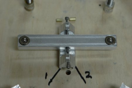
Here we can see the beam with ball transfers at both ends, and small ball bearings in the middle.
An axle runs through the bearings and is "caught" by two 4-40 screws. The beam will move when
about 1/3rd of a grain (0.02 grams) is placed on either end--that is: low friction and good balance.
The imbalance is also the maximum amount of force the beam cam impart into the back of the
mirror at any elevation.
The beam is surprisingly stiff in deflection and in twist being supported only on the 1/8" axle and
located by the 4-40 socket head screws.
In order to properly locate the beams, brass tubing was cut and filed to thickness. This gets rid of
the lateral movement of the beams due to the sloppy fit of the axle to the inner races of the bearings,
but hampers the ability to move the beams inward or outward finding the perfect support radius.
At the top of the image are two little brass tubes used to space the beams on the axle:
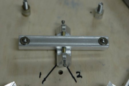
Originally the axle was supposed to hold the bearings stiffly enough that no spaces were required,
and that the beams could be moved laterally with the 4-40 screws. But this is where this build ended
up.
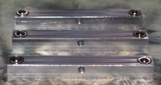
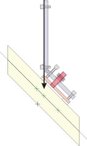
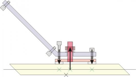
In order to attach the brackets to the Y-frame, I machined in some relief slots at precise angles on
the bottom of the brackets so the brackets would practically grab the metal on the Y-frame. each
slot was carefully positioned to pass through the center of the bracket. As to the brackets grabbing
onto the Y-frame--yes they did.
With all of this machining and tight tolerances, at some point or another one has to question whether
this whole thing can be assembled and have any fidelity to the original design point. In order to address
the tolerance stackup, I built a wooden support plate with precisely located holes and machined up some
collars to hold the beam ends at exactly the right positions. This plate eliminates tolerance stackup, only
to expose your machining flaws.
Guess what? Remember that drills do not drill straight, well the beam axes are not exact, nor are the 4-40
screws in the bracket exact. Grrrr.
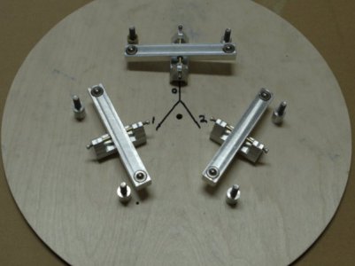
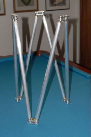
Here we see all 3 brackets face forward on the alignment plate which <all but> eliminates tolerance
stackup. The beam point positions are entirely determined by the support plate bushing locations.
These can be measured (and have been) and are within about 0.002 or correct.
We can also see that the beams are in balance and that none are touching the support plate nor their
bracket mid-section.
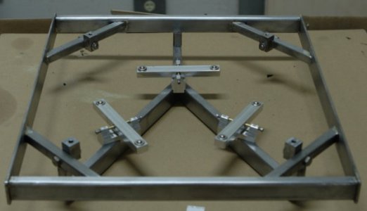
Now, I remove the ball transfers, flip the brackets over and press them onto the guide bushings:
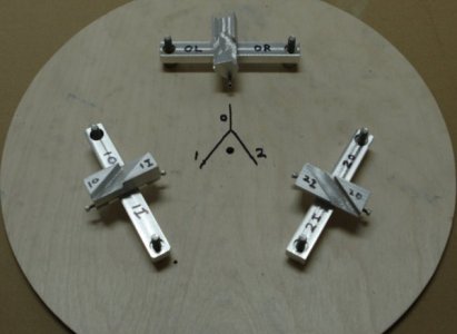
At this point, the Y-frame can be dropped into the bracket slots which have been relieved so that
the both the bracket and Y-frame can jiggle about 0.001-0.003". Just enough to prevent stress from
<ahem> repositioning the support points on the ends of the beams.
When the upper part of the mirror cell is ready, the Y-frame will be trimmed to length, sanded, and
painted (gloss black) and when dry, the brackets will be epoxyed onto the Y-frame while being held
on the support plate. Now, the ball transfer roller balls will be precisely positioned.
You might notice that brackets and beams are labeled. Once the brackets are epoxyed to the Y-frame,
each beam goes in exactly one direction, one other thing is that the ball transfers are also "indexed"
nto a particular hole in a particular beam (they weigh differently--at the scale these beams can judge
weight 0.3 grains).
So, a tale of woe is finally solved by a bit of cleverness.
Some observers might say "Why go to so much trouble". There are 2 responses to this: 1) It's my telescope,
2) I am trying to build it more like a Swiss watch than a John Dobson Dobsonian. There is also a third reason:
Mike Lockwood has been writing about telescope mirror cells stating that low friction is key to making thin
light mirrors work.
This build is an experiment in how low a friction a mirror cell can have (thus ball transfers supporting the back
and sides) and ball bearings supporting the beams. In the scale amateurs can achieve, this is pretty close to a
little friction as reasonably achievable.
Some might ask if this is Overkill--Absolutely! it is!
But as an experiment in low friction cell design, in a low (wind) profile frame design that allow essentially unfettered
air to the back and sides of the mirror itself. See later.
The mirror cell is a square with two 1/2×1 mild steel tubes 14.5" long and two 1.25×1/8 flat steel silver brazed into a
square. It was a conscious decision to position this frame fully surrounding the mirror itself. Each edge supports
transfer their loads to a frame stiffening member. The frame stiffening member is then silver brazed to the mirror
cell and the mirror cell is screwed directly onto the altitude bearings.
The Y-frame has been calculated to heave on-the-order of 0.001" from zenith to the horizon--well within the
focusing tolerance of an F/3 scope. The frame stiffeners are considerably stiffer considering the 10.6 pound weight
of the mirror.
The mirror cell will be directly attached to the altitude bearings leaving no intermediary way to lose stiffness.
The edge supports are ball transfers sitting in a fixture. On the top of the fixture is a threaded hole which will be
used to hold the top edge restraint (so the mirror cannot fall forward out of the mirror cell.) At the back of the fixture
is a 1/4-20 thread so the fixture can be bolted to the frame stiffener. The height of the fixture above the ball transfer
was sized so that when the mirror is touching the edge restraint the ball transfer should be exactly at the CoG of the
mirror.
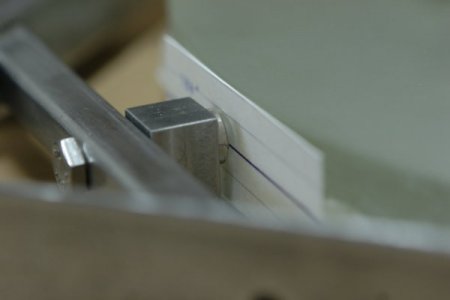
Here we see the bolt holding the fixture to the frame stiffener holding a ball transfer.
