2014 POTD Thread Archive

That lift is slick, care to share the plans/dimensions?

I just dreamed it up laying in bed the other night and the dimensions are pretty much whatever the size of the hoist is, I didn't draw any plans, just enough to make sure I marked and drilled the pieces in the right spots. I measured several times from the center of the arm pivot bolt to what is normally the chain attachment point, it was, I think 53 15/16". I say think as my pad with the dimension is in the shop an I'm not leaving the warm fire to grab it. ;) The key is making the lower arm the same center to center distance as the main arm so it acts are a true parallelogram. This of course applies to the vertical arms. I ended up making these with 12.5" centers. The one on the business end has the top hole 6" from the pivot pin. I figured 2x that distance for the arm would give it enough leverage to hold any load I'm likely to use it for. I added a few cross pieces using 1/2" bolts and some conduit for spacers. Nothing fancy, just some 1/2 and 3/8" bolts. I did use locking insert nuts for the pivot points so I could adjust the clearance while still moving freely.

I used a piece of peg board as a jig for marking the lines on the upright, I just drilled a 1/2" hole in the pegboard and stuck a bolt through the support brace holes on the upright, drew an arc with a sharpie in a pegboard hole and used a square set to 1" from the front face to mark the intersection. That distance turned out to be 12.5 and thus became the vertical support dimension. Seat of the pants engineering.

mike
 
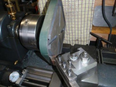
I had noticed that my big drill press wasn't giving me vertical holes, so today was the day to try to true it up. The table had been finished with a pass from a very large flycutter or face mill - something around 16" diameter judging from the tool marks. Checking with a square showed that the table needed to 'nod' to true up front to rear.

Since I now have a lathe that's big enough (the table is almost 14" diagonally), I decided to face the table. Because of the large diameter, I needed to use carbide at the slowest lathe speed to get an acceptable cutting speed for the cast iron table. The brazed carbide cutter has a 1" shank and is very solid - necessary due to the interrupted cuts.
attachment.php?thumbnail=7800.jpg

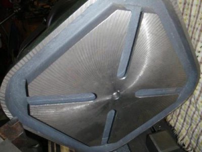
You can see the original tool marks, especially on the rim at the top.
attachment.php?thumbnail=7801.jpg

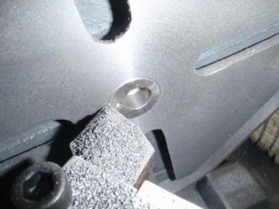
As shown, the centre hole was a bit off centre. A touch-up with a boring bar made short work of that.
attachment.php?thumbnail=7802.jpg

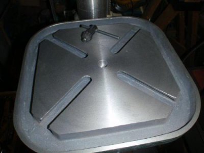
Shimming with aluminum foil at the top of the table support arm gave enough nod to level the table. A much nicer finish than the original.
attachment.php?thumbnail=7803.jpg
 
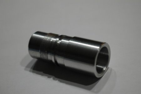
A friend wanted a custom tip for a paintball barrel... The trick being that the thread has a double lead.

DSC_2317_422net.JPG

DSC_2317_422net.JPG
 
Not really machined but certainly a product of my shop. The old saying that necessity is the mother of invention, certainly true in this case. Last weekend I purchased a 125,000 BTU Modine propane heater for the shop, trouble is mounts to the ceiling that is 9.5 feet up, weighs about 125lbs and is large and bulky. It occurred to me that I might be able to re-purpose my engine hoist (PepBoys/HF). A few hours in the shop and I have a hoist cum lift. I am quite happy with how it turned out, the platform stays nearly dead level over the length of travel. Of course I won't put anything really heavy on it but I did carefully have a seat on it and nothing felt shaky, I am not a small guy, so I am confident it will handle the heater without a problem. I used an old sub woofer cabinet as a test, figured it that fell off I just didn't care.

View attachment 70888

View attachment 70889

View attachment 70890

[video=youtube_share;kVsDfK76dp8]http://youtu.be/kVsDfK76dp8[/video]
that is so cool,thanks for showing
 
I just dreamed it up laying in bed the other night and the dimensions are pretty much whatever the size of the hoist is, I didn't draw any plans, just enough to make sure I marked and drilled the pieces in the right spots. I measured several times from the center of the arm pivot bolt to what is normally the chain attachment point, it was, I think 53 15/16". I say think as my pad with the dimension is in the shop an I'm not leaving the warm fire to grab it. ;) The key is making the lower arm the same center to center distance as the main arm so it acts are a true parallelogram. This of course applies to the vertical arms. I ended up making these with 12.5" centers. The one on the business end has the top hole 6" from the pivot pin. I figured 2x that distance for the arm would give it enough leverage to hold any load I'm likely to use it for. I added a few cross pieces using 1/2" bolts and some conduit for spacers. Nothing fancy, just some 1/2 and 3/8" bolts. I did use locking insert nuts for the pivot points so I could adjust the clearance while still moving freely.

I used a piece of peg board as a jig for marking the lines on the upright, I just drilled a 1/2" hole in the pegboard and stuck a bolt through the support brace holes on the upright, drew an arc with a sharpie in a pegboard hole and used a square set to 1" from the front face to mark the intersection. That distance turned out to be 12.5 and thus became the vertical support dimension. Seat of the pants engineering.

mike
I'm loving that lift mod too. What a great idea! :))

Marcel
 
Well today I continued on with my Z-axis CNC conversion parts.

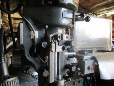
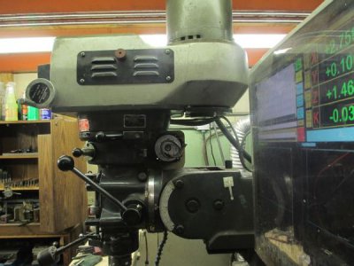
I made the cable bracket for the quill counter balance, not a big project for the day but I also got to test out the rebuilt spindle by putting a little load on it. This is the first I have had a chance to load up machine a bit since I went through the entire head.

I had the spindle rebuilt with the 5 bearing upgrade and had the taper reground by C & M PRECISION SPINDLE, INC. in Tualatin, OR. http://www.cm-spindle.com/home.html. I'm very happy with the job they did.


The quill counter balance is to take up the play that will be introduced by the gear train when I install the Z-axis drive hardware. If you would like to see more on this subject, go here: http://www.dawsoncontrols.com/millupgrade.html. I don't think anyone has done it this way before.


Anyway, the POTD

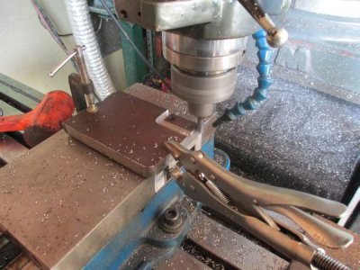
I grabbed a chunk of 5/8 A6 I had on the shelf to make the part. First I drilled the mounting holes and bolted the piece to a piece of aluminum flat bar. This allowed me to profile the entire outside of the part.

cboutside.jpg


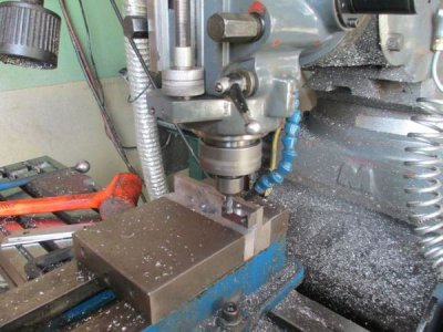
Then I flipped it up and milled the front profile.

cbfront.jpg


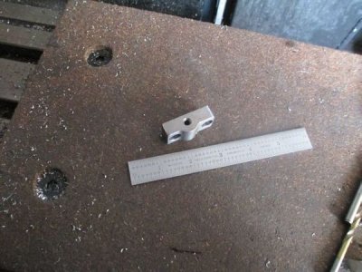
The finished part

cbfinished.jpg

Installed on the head

cbinstalled.jpg

The preparatory work for this can be seen at: http://www.hobby-machinist.com/showthread.php/21060-Z-axis-CNC-Conversion

Tomorrow I will machine a mockup of the gear case out of some MDF just to check the fit before I start carving it out of a rather expensive chunk of aluminum.
 
Well today I continued on with my Z-axis CNC conversion parts.

I made the cable bracket for the quill counter balance, not a big project for the day but I also got to test out the rebuilt spindle by putting a little load on it. This is the first I have had a chance to load up machine a bit since I went through the entire head.

Very cool, looking forward to seeing it all completed.
 
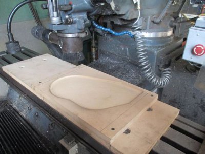
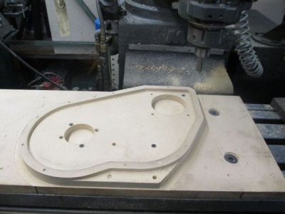
Today I made a mock up of the gear case for my Z-axis CNC conversion. I made it out of 3/4 MDF, the actual gear case will be 2" thick aluminum. MDF is pretty stable, and easy to machine.

First I bolted a piece of MDF to the table, then screwed the work piece to it. Makes a good work holder and that way I have a buffer in case I cut a little too deep, or do something else stupid. Many time I use MDF or plywood as a base even when metal.

I used a 1/2" carbide router bit for this work.

The inside pocket

gcinsidepocket.jpg

The finished mock up
gcfinished.jpg


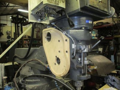
It fits!!!!
gcmounted1.jpg

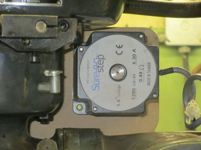
The step motor clears everything, was is the main reason for the mock up. All the screw holes lined up too!!

stepmotor2.jpg

A wider view

stepmotor1.jpg

See the whole project at [url]http://www.dawsoncontrols.com/millupgrade.html[/URL]
 
That is a great looking piece! I like your dust control system for cutting the very dusty MDF!

Your site looks great also. I will read it all when I get a chance. That shot of the CAD drawing over layed on the picture....genius! Never seen that before.
 
Back
Top