24 inch finger brake

Do you have pictures of the build process? I’ll bet many members here would be interested in following along with how that progressed.

Nice work! Really impressive finished project!


Sent from my iPhone using Tapatalk
 
It looks like there was some welding involved. How much and where? I am not a welder, so I cringe at the press brake I built with welding. If the welding was only the feet, I might want to make one, too. Your work is inspirational.

joe
 
It looks like there was some welding involved. How much and where? I am not a welder, so I cringe at the press brake I built with welding. If the welding was only the feet, I might want to make one, too. Your work is inspirational.

joe
The welding was minimal. Maybe 10 inches of weld, and luckily, most of the welds are well hidden as this was the first time I powered up the welder in about 2 years so my welds don't look perfect but they are plenty strong enough. I used my buzz-box tig setup with a hi-freq arc starter.

Matt
 
I finally completed my build of the 24 inch brake from plans by Michael Ward and published in HSM a few years ago. So far I have bent 16ga aluminum at full width with no difficulty.


View attachment 336664 View attachment 336665

Matt
Wow...!!! Beautiful workmanship.

I am not trying to hijack the OP thread and I hope that the following might help others that are looking at finger brakes.

  • What is the radius at the tip of the fingers that you made?
  • What materials are the fingers made from?

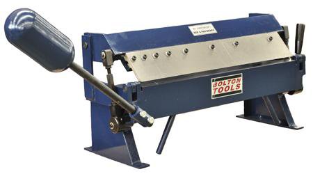
I am asking because I bought this brake few weeks ago - https://boltontool.com/sheet-metal-machine/break-press/PB2416

pb2416 c.jpg

The price was right and it is actually pretty good except for the steel fingers that are very sharp with practically no radius at the bending edge. This is OK for very thin material but for 18 GA CR steel or 16 GA aluminium it causes cracks in the material. So rather than modify the original steel fingers I decided to make an additional set of fingers from 7075 material that seems very strong and easy to machine. I made one finger with 0.125" radius and the results are beautiful.

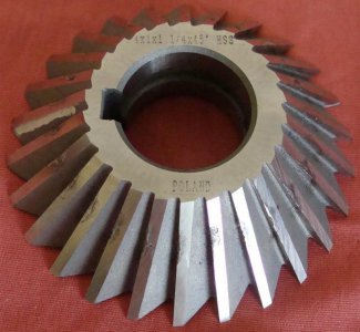
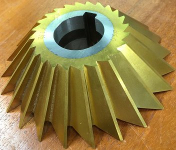
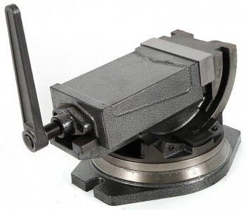
I am now making the rest of the wider fingers which represent minor challenges on how to properly do it on my PM833T milling machine. There are 45 degrees edge angles that can be done by several methods:
  • 45 degree milling cutter 45 deg cutter 2.jpg 45 deg cutter.jpg


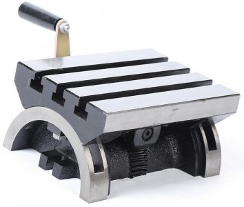
  • or by putting the material in 45 degrees in the vise or a tilting plate Rotating and Angle Vise.jpg Swivel Angle Plate Tilting Table.jpg


  • or... if I had a full size BP type milling machine by tilting the head upward in 45 degrees
Not sure what is the best method, I am open to suggestions. Luckily this is a hobby and I enjoy the challenges and the solutions.

Ariel
 
Wow...!!! Beautiful workmanship.
  • What is the radius at the tip of the fingers that you made?
  • What materials are the fingers made from?

Ariel

The side frames, bending plate and fingers are all made from half-inch cold rolled steel. Per the published plans, I kept the sharp (approximately 40 degree) edge on the fingers as I wanted sharp inside corners. You can always add a radiusd piece of material at the end of the clamping fingers. I used the tilting table on the BP mill.
 
You can see a fairly detailed build log for something similar to these by a long-time, amazingly-good craftsman from this forum. Mark_f made one back in 2016. (Searching for the articles from the Home Shop Machinist magazine actually led me back to this forum.)
 
Matt... that is a beautifully made finger brake. You should be very proud sir. I know I would. And every time I used it, I’d feel so damned good because I made it. Beautiful tool.
 
To the OP, I searched around and was unable to find the original HSM article or the plans. I also tried searching on " Michael Ward" and "brake" but still came up empty handed. It's been pretty long since the article came out, where did you get the plans and are they still available?
 
I wonder what it would take to make it capable of bending 1/8"brackets up to a couple inches wide—maybe it does now. I built two cars from scratch and had to bend a lot of metal, and the most annoying ones were the 1/8" brackets, hammering them over in a vice. The thinner gauge bends weren't as "memorable", in that they were fairly easy to bend clamped between two pieces of 4" I-beam.
 
Last edited:
I wonder what it would take to make it capable of bending 1/8"brackets up to a couple inches wide—maybe it does now. I built two cars from scratch and had to bend a lot of metal, and the most annoying ones were the 1/8" brackets, hammering them over in a vice. The thinner gauge bends weren't as "memorable", in that they were fairly easy to bend clamped between two pieces of 4" I-beam that are kept just for that purpose.
I've been playing around with the brake over the last couple of days. I can successfully bend 1/8" steel up to 6" wide with the current setup. I've also learned to produce different size bending radius by adjusting the clamp bar. I even did some bump bending to produce large radius bends and lastly I made some accessories to easily create hemmed edges.

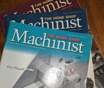
The plans from HSM were over 10 years ago as a 3 part article. Here are the issues:

HSM.jpg

Matt
 
Back
Top