Hello,
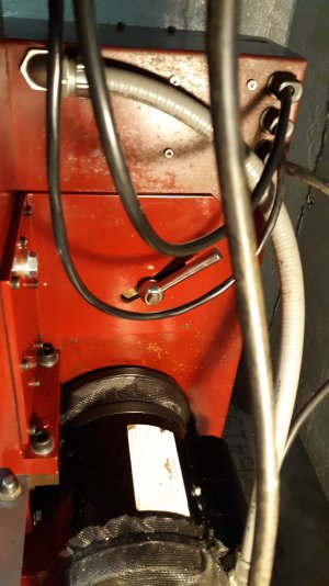
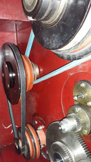
I have a Bolton BT800 3-in-1 combo machine. It is the same as the Grizzly G9729. I use it for hobby stuff and have enjoyed it reasonably well. I have mostly used it for milling stuff, which has it’s own issues, but this question is about the lathe. I have turned a few things on it, but I never had need to change the speed until yesterday. I can't seem to figure out how to tension the belts. Every time I try, I am able to tighten the bottom belt but this loosens the top belt. Is there a correct order or something for positioning or clocking the pulley so I can get both belts tensioned?
I get (I think?) how it is SUPPOSED to work. My thought is that the pulley is initially placed somewhere along the slot, then things are tightened up with the fastener, which would pull the pulley against both belts.
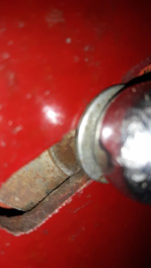
I was hoping someone can explain to me a proper procedure to use when changing these belts around? I have been fighting with this for hours. I even ground a slot into the stud that comes out of the other side of the pulley, which does make it easier to clock the pulley with a screwdriver, but I still can't seem to figure this out.
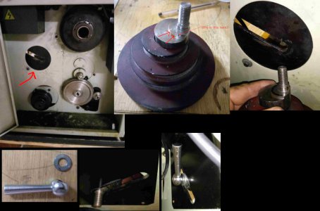
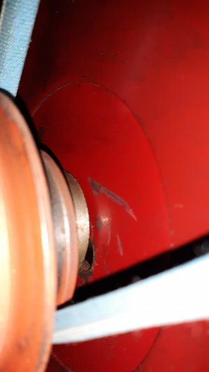
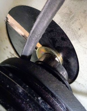
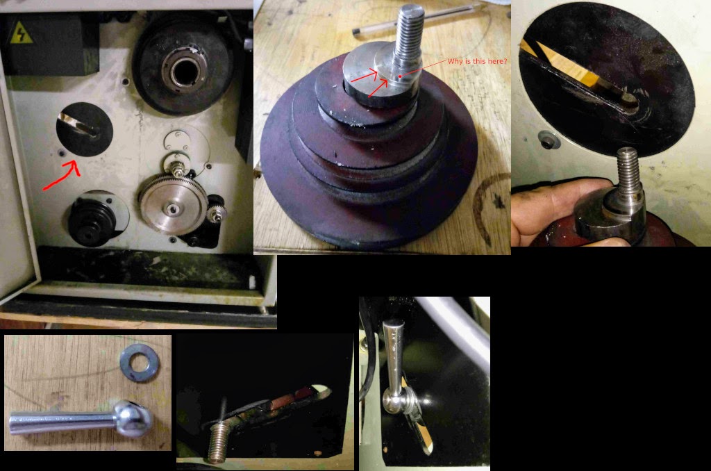
Okay, so the first picture shows where the pulley stack goes. The second picture is the stack, removed from the machine. Why does it have this extra raised surface on the mounting surface? I don't understand what that is for. The third picture is just a closeup of the mounting surface next to the pulley. The last three pictures are of the fastener that goes on the stud and how it mounts to the other side.
I hope my this makes sense. Theoretically you should be able to see the image above, let me know if you can't ...
I have a Bolton BT800 3-in-1 combo machine. It is the same as the Grizzly G9729. I use it for hobby stuff and have enjoyed it reasonably well. I have mostly used it for milling stuff, which has it’s own issues, but this question is about the lathe. I have turned a few things on it, but I never had need to change the speed until yesterday. I can't seem to figure out how to tension the belts. Every time I try, I am able to tighten the bottom belt but this loosens the top belt. Is there a correct order or something for positioning or clocking the pulley so I can get both belts tensioned?
I get (I think?) how it is SUPPOSED to work. My thought is that the pulley is initially placed somewhere along the slot, then things are tightened up with the fastener, which would pull the pulley against both belts.
I was hoping someone can explain to me a proper procedure to use when changing these belts around? I have been fighting with this for hours. I even ground a slot into the stud that comes out of the other side of the pulley, which does make it easier to clock the pulley with a screwdriver, but I still can't seem to figure this out.
Okay, so the first picture shows where the pulley stack goes. The second picture is the stack, removed from the machine. Why does it have this extra raised surface on the mounting surface? I don't understand what that is for. The third picture is just a closeup of the mounting surface next to the pulley. The last three pictures are of the fastener that goes on the stud and how it mounts to the other side.
I hope my this makes sense. Theoretically you should be able to see the image above, let me know if you can't ...