5C Collet Drawbar

I hijacked this from another site. The person that posted it apparently worked for Hardinge or had inside contacts that got him this information.

In some of the older Machinery's handbooks, like the 11 th or 12 th edition, they have a couple of pages devoted to the different collet types and some of the basic dimensions for identifying.

If you dig deep enough on Hardinges website, they used to have some dimensional information available, too.

Ken
 
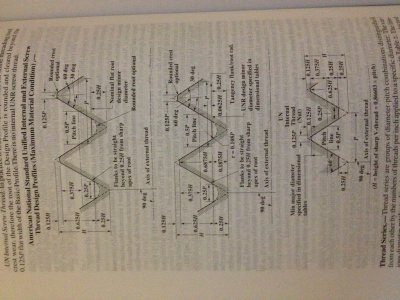
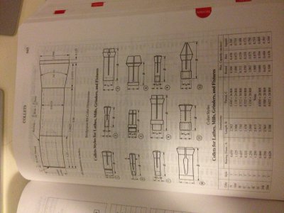
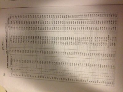
Got the Machinery Handbook out tonight, and found the dimensions for the threads, as well as the 5C collets.

On Page 1720, 28th ed. Dimensions and relationships of 60deg threads.
Photo Aug 18, 3 30 22 AM.jpg

On Pages 945+946, 28th Ed. Dimensions of standard collets.
Photo Aug 18, 3 35 11 AM.jpg

Photo Aug 18, 3 35 37 AM.jpg

As far as exactly how large you should cut the bore, prior to threading. It looks like the minor diameter (bore) of the internal threads should be 1.218, prior to threading. (1.238-(.375*H)*2, H being .027, the depth of the thread) I have never had the thread "grow" on any threads that I have machined. If this is happening, make sure that your bit is sharp , or use a file with emery cloth on it to bring the diameter down. You may just be experiencing burs that accumulate on the crest of the thread, or the thread is not yet large enough.

If you choose to feed the tool in with the compound, be sure to compensate for the angle of the tool when calculating depth. depth * (1/sin(60.5) = adjusted feed number for compound feeding. This equates to 115% of the depth, for unified standard threads. So in this case you would need to feed the compound in .031" to get the true depth of .027".

Good luck, ill be watching closely to see how it goes.

-Cody

Photo Aug 18, 3 30 22 AM.jpg Photo Aug 18, 3 35 11 AM.jpg Photo Aug 18, 3 35 37 AM.jpg
 
Last edited:
Cody, If my calculations are correct, you're saying that the bore should be 1.228. I'll try that on a scrap piece and see if it works out better. I used the dimensions Ken posted above. I bored it 1.1875. I cut the threads until my hardinge collets threaded in nice and snug. The import collets fit kind of loose, but I don't have many of them and they will be replaced at some point. Thanks to all for the input.

Chuck
 
Bore diameter changes slightly depending on class of fit. The lower diameter you used is probably closer to the 3B class.

The basic math is

Clearance = OD * %ofthread / TPI

Bore ID = OD-Clearance

So at 80% thread engagement you get 1.188
 
My favorite handy-dandy formula is: BoreDiameter = BoltDiameter - 1.15/Pitch.

In your case: 1.238 - 1.15/20 which equals 1.181. This will give you a 100% engagement so, what you need to do is thread it until you get the correct depth then, take a couple thou off the crest. Works for me every time. BTW, the inserts I use have a leading edge that automatically starts trimming the crest off once you reach the proper depth. Each insert is designed for a particular pitch. For general purpose work, I just use a very large insert that cuts an 8TPI thread so, in that case, I have to cut the crests off manually because the point is much longer than needed for any thread with a pitch finer than 8. When I'm doing work to spec, I use the appropriate insert and always end-up with a very high-class (high end of class II usually -almost class III) fit. The boat propeller shafts I make/refurbish are almost always 16 or 18 TPI class II (if they're US thread). BTW, class III threads are pain in the butt -way too finicky. For the most part, I think class III is not for fastening but more for calibrated/threaded measuring instruments and the like...

Ray
 
Cody, If my calculations are correct, you're saying that the bore should be 1.228. I'll try that on a scrap piece and see if it works out better. I used the dimensions Ken posted above. I bored it 1.1875. I cut the threads until my hardinge collets threaded in nice and snug. The import collets fit kind of loose, but I don't have many of them and they will be replaced at some point. Thanks to all for the input.

Chuck

Hey Chuck,

I forgot to account for the depth on the other side of the thread as well. The Diameter according to the formula should be 1.218. Everything else should be the same. I corrected the formula in the original post. It now reads, (1.238-(.375*H)*2, H being .027, the depth of the thread)

Sorry for any confusion.

It is interesting the 1.1875 bore fit the threads tightly. Something does not make sense here... Perhaps the measurement (1.238") is not the pitch diameter? I am going to do more research.

-Cody
 
My old ANSI standard (pre-unified system) says nominal diameter- .0541" = bore diameter minimum. With a tolerance of plus .0054"

Which comes out to 1.199/1.204" bore diameter.

The Newer ANSI Unified system says

Thread bore diameter =
Minor diameter, minimum = nominal-1.08253*p
Minor diameter, maximum = Minor dia. min.+.25*p-(0.40*p^2)

Which comes out to 1.199/1.210 dia. This applies to both class 2 and 3 threads.

The unified system gives more tolerance on the bore diameter.

I used to know all this by heart 20 years ago when I was involved in writing standards for the company I worked for back then. Even though I still use it, its now in a Excel spread sheet so I don't have to hand crank calculation anymore.

Ken
Ken
 
Ok. I see where I went wrong.

It has been too long since the last time that I read a technical drawing, and forgot that thread class size is the major diameter of the thread, not the Pitch diameter.

So in this case, 1.238" is the diameter of a shaft ready to be turned for External threads. From there, you would subtract the double depth of the threads, .054", to get the minor diameter of .184". The pitch diameter would be the major diameter minus half the double thread depth. Or 1.238 - .027 = 1.211. Therefore, according to the formula, the ID before threading should be 1.191". The Handbooks' formulas take into account a small flat on the crest, which accounts for the difference in the drawing from Hardinge, and the calculated number.

This makes much more sense to me. I apologize if I threw anyone else off track.

-Cody
 
BTW, that formula below also works for tapping a hole but, you need to take that final number, convert it to 64th's and round up to the next whole 64th inch. Stick the tap in the hole and go for it. Works every time and the final size will be in-agreement with any standard tapping chart.

Of course, if you're threading on a lathe, you're not worried about breaking a tap so, just bore a hole to the number you derive with the formula, get the boring bar out and start threading until you hit the right thread depth -then, knock off the crest (because they're useless and problematic anyhow).

I don't do as much threaded boring as I do external shafts but, I've done it 10 times more than I can count and it always works. I derived that little formula myself -and I'll be darned if I remember how but as I recall, it had to do with 1.15 being the reciprocal of the cosine of 30 degrees. Maybe I'll find the scratch paper I used to sketch it all out and derive that -but I won't bother to derive it again because it just works...


Ray
 
Ray, I bookmarked your formula. That will save me a lot of time..and guessing. I've never tried inserts for threading. I guess when the drawer full of hss bits runs out or my eyes get so bad I can't see to grind them, maybe I'll think about buying some. Thanks

Chuck
 
Back
Top