7.5HP RPC

Braeden P

Registered
Registered
Joined
Sep 1, 2020
Messages
1,591
I just got two 7.5 hp 3 phase motors from my uncle, I’m using the better one for a RPC. I have a 60 amp 220 volt circuit running only the RPC. Will this wiring diagram work. The switch I am using is rated for 7.5 hp 3 phase and I’m using 8 gauge wires for all of it. The highest HP machine being powered is a 3 HP lathe, I hope to be able to run the lathe and 2 HP mill at the same time without having issues.IMG_6033.jpeg
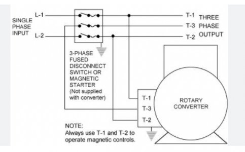
 
That is the basic wiring diagram for a RPC. What it is missing is some way to bring the idler motor (labeled rotary converter in your diagram) up to speed. Usually a start capacitor(s) are connected at startup to get the idler up to speed then disconnected when the idler is running full speed. Some RPC's will use a single phase "pony" motor to bring the idler up to speed and then mechanically disconnect to pony motor when the idler is running at full speed.

Many RPC's will also have run capacitors that balance the voltage between the 2 supplied legs (L1 and L2) and the generated leg (L3). These are more optional than required.

Once a machine is up to speed the machines motor contributes to generated leg as kind of an auxiliary idler. As long as you don't start up the lathe and mill at the exact same time (simultaneously hit the start buttons) you should be fine. Wait until one machine is up to speed before starting the second machine, you should then be able to run them both under load at the same time. If you are a one man shop you can have a dozen 3ph machines connected to the phase converter and use them each sequentially.
 
Last edited:
i WOULD NOT CALL THE (RUN, OIL FILLED CAPACITORS "OPTIONAL" TO MAKE A UNIT THAT PROVIDES A SMOOTH START AND RELATIVELY BALANCED VOLTAGES, THEY ARE NECESSARY, NOT OPTIONAL. PLEASE EXCUSE THE ALL CAPS FORMAT, CAP LOCK GETS STUCK ON AND I'm TOO LAZY TO RETYPE IT.
 
I knew of a one man shop who pull started his RPC by wrapping a belt around the shaft.
 
I know a guy that is running his whole shop on a 60hp RPC. He has a 5hp pony motor on a hinge with a long stick on it. He puts a belt on between the two motors, tensions the belt with the stick and starts the 5hp pony motor. When the 5hp is up to speed he turns on the 60hp, slacks the belt which then goes flying, bouncing all over the room. I was pretty mortified when I first saw the procedure in action. He has been doing it this way for 30 years without any issues, every morning. No balancing capacitors, no problems.

His main business is running a huge pellet mill that he uses to make gopher and mole bait / poison. He has several other machines though including a CNC mill that he mostly uses for fun.
 
Last edited:
i WOULD NOT CALL THE (RUN, OIL FILLED CAPACITORS "OPTIONAL" TO MAKE A UNIT THAT PROVIDES A SMOOTH START AND RELATIVELY BALANCED VOLTAGES, THEY ARE NECESSARY, NOT OPTIONAL. PLEASE EXCUSE THE ALL CAPS FORMAT, CAP LOCK GETS STUCK ON AND I'm TOO LAZY TO RETYPE IT.
I have an old RPC with a blown motor, I will test those capacitors and if they still work see if they are big enough to run the motor. I have a 280V 326 uf start capacitor that I can rig up to start it.
 
the 7.5 idler is sufficient to run a 3 and a 5 hp motor simultaneously
as mentioned, a a contactor , a normally open switch for starting, a normally closed stop switch , and a start capacitor of more than 500 Uf is necessary for function
 
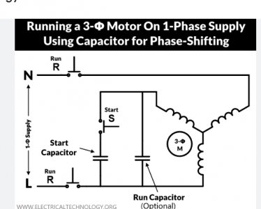
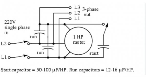
This is what is confusing me about the run capacitor(s). If I run one I have to wire it from line 1 to three like in the first picture and if I use two I have to wire it like the second picture? The start capacitor is wired the same way in all of the diagrams I can find.IMG_6034.jpeg(I know the run capacitor is needed)IMG_6035.jpegThis one shows a second run capacitor between line 2 and line 3.
 
The start cap always connects from the new (3rd) leg to one of the incoming power legs. Whether it's L1 or L2 sets the start direction which usually doesn't matter. A momentary switch disconnects the start cap after the motor is at speed, to prevent overheating and lengthen its life, and allow the 3rd leg to assume its nominal induced voltage

Then additional balance caps as needed, from new leg to incoming lines 1 and/or 2 until the 3 output voltages are roughly equal when load machine is connected- often the system will work well enough without additional balancing caps
 
Last edited:
For your needs, just a single start capacitor will be fine.
You won’t notice the difference for what you are doing.
You will have a leg that has been induced and it will have lower voltage than the other two supplied legs.
Use the supplied legs to operate controls snd do not ise the generated leg for circuits that connect to transformers.
 
Back
Top