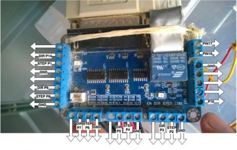
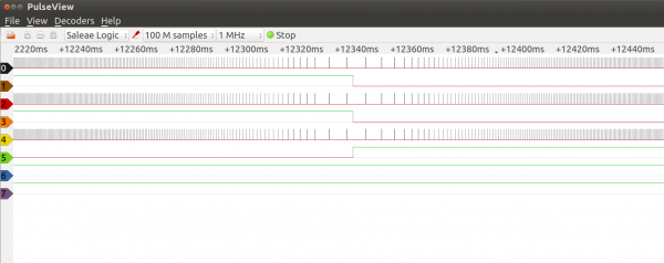
I'm not doing anything that hasn't been done before but at the request of brave_ulysses I'm starting a thread on my conversion of a 7 x 12 mini lathe. The basis of the conversion is a run-of-the-mill Asian mini lathe that I picked from a lady that was disposing of her recently deceased father's possessions. The lathe was new but absent the accessories except a three jaw chuck. The stepper motors (270 oz in), drivers (DQ542MA) and power supply (350W/36vdc) are from Wantai Motors. I've had good reliability with the Wantai equipment I purchased for my vertical mill conversion five years ago so decided to go the same route on the lathe. The breakout board is a leftover from my mill conversion as is the UC100. Ball screws and ball nuts were purchased from Linear Motion Bearings. Here are a few pics of my progress so far.
As you can see the X and Z motors are mounted and are coupled to 1605 ball screws with double ball nuts. Another ball screw bellows is on order and should be here in a couple of weeks. Please disregard the wiring mess. I just started the wiring to get everything working. Once I'm satisfied with the results I'll tidy it up.
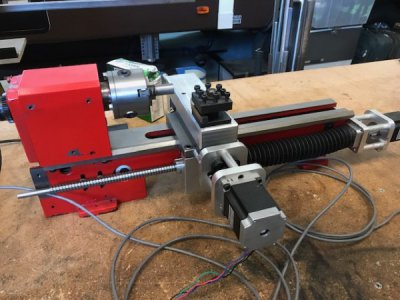
A closeup of the X axis mounting brackets. The only original remaining moving component is the saddle. The picture doesn't show the new saddle gibs I made nor the machining I had to do on the saddle to get them to fit correctly. Evidently the factory deemed it not important to machine the gib mounting surfaces and used a hand grinder instead.
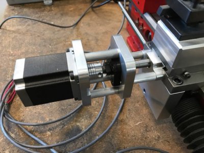
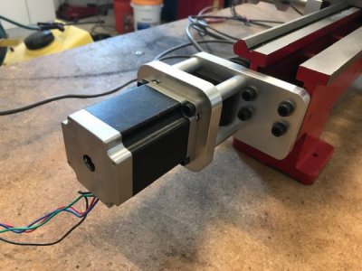
Here's a shot of the Z axis mounting brackets. This picture doesn't show it but I setup the lathe bed on my milling machine and machined the end of the bed so the bracket had a flat and perpendicular surface to mount to. Setting up the lathe bed in the mill was a real PITA.
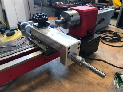
Here's a back side pic of the X axis screw and nut. A cover will be made to keep chips off the ball screw. The cross slide riser is made of 7075 aluminum. I'm mentioning this because it's the first time I've machined this stuff. It's a lot tougher than 6061.
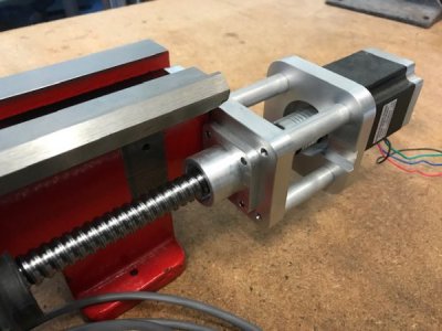
Another view of the Z axis mount. If you look closely you can see a groove cut in the face of the stepper motor mount. This was a "doh" moment when I assembled the motor and realized I couldn't get to the coupling clamp screw and set screws.
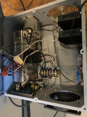
Still a work in progress but a pic of the control cabinet. Most of the test wiring is complete. Still need to wire in limit switches and the e-stop. Powered up the system to see if the motors would turn but got driver red alarm lights. I need to go back and double check all my control wiring.
As you can see the X and Z motors are mounted and are coupled to 1605 ball screws with double ball nuts. Another ball screw bellows is on order and should be here in a couple of weeks. Please disregard the wiring mess. I just started the wiring to get everything working. Once I'm satisfied with the results I'll tidy it up.

A closeup of the X axis mounting brackets. The only original remaining moving component is the saddle. The picture doesn't show the new saddle gibs I made nor the machining I had to do on the saddle to get them to fit correctly. Evidently the factory deemed it not important to machine the gib mounting surfaces and used a hand grinder instead.

Here's a shot of the Z axis mounting brackets. This picture doesn't show it but I setup the lathe bed on my milling machine and machined the end of the bed so the bracket had a flat and perpendicular surface to mount to. Setting up the lathe bed in the mill was a real PITA.

Here's a back side pic of the X axis screw and nut. A cover will be made to keep chips off the ball screw. The cross slide riser is made of 7075 aluminum. I'm mentioning this because it's the first time I've machined this stuff. It's a lot tougher than 6061.

Another view of the Z axis mount. If you look closely you can see a groove cut in the face of the stepper motor mount. This was a "doh" moment when I assembled the motor and realized I couldn't get to the coupling clamp screw and set screws.

Still a work in progress but a pic of the control cabinet. Most of the test wiring is complete. Still need to wire in limit switches and the e-stop. Powered up the system to see if the motors would turn but got driver red alarm lights. I need to go back and double check all my control wiring.


