- Joined
- Feb 7, 2018
- Messages
- 162
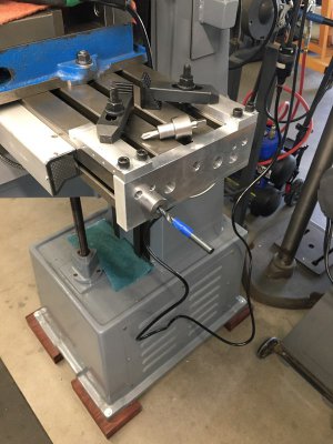
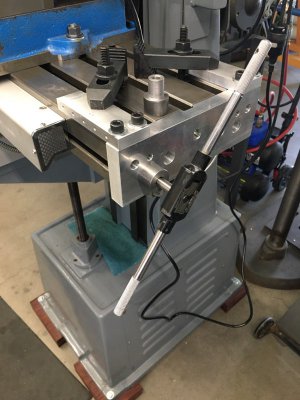
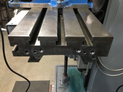
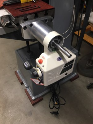
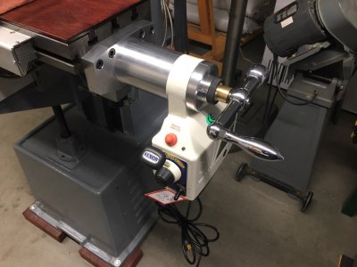
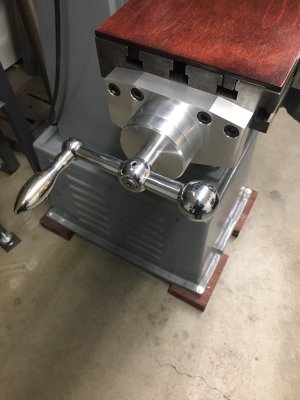
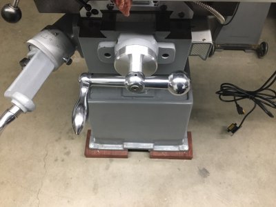
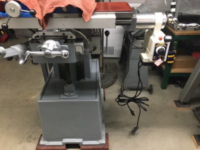
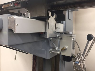
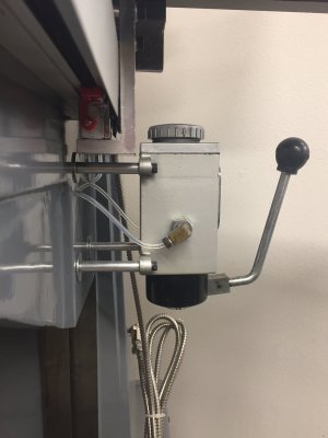
I've had an 8x30 x-axis power feed modification on the back burner for quite sometime now and I'm getting close with the project being complete. A goal of this project was to also replace the leadscrew bearing blocks on either end and align the leadscrew which was not parallel to the table. The original bearing blocks attached to table ends with just two M6 SHCS and this seemed just a little undersized so I wanted to upgrade those in the process. Unfortunately I didn't photo document the whole process but got enough to show the project. The first step was to determine the location of the leadscrew relative to the table to be able to design the new end bearing blocks. This really wasn't a hard step and just involved some indicators on either end of the leadscrew to determine it was straight passing though the lead nut. With known dimensions I modeled the table up in CAD and designed the power feed add-on. Because of how my mill Y-axis DRO scale and one-shot oiler are mounted I had to mount the power feed further off the table end for interference reasons.
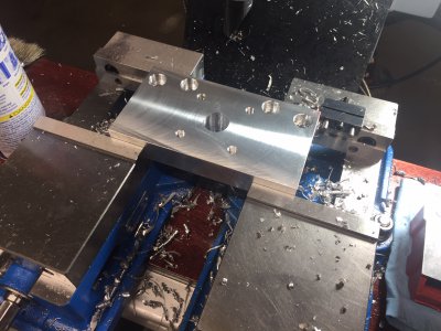
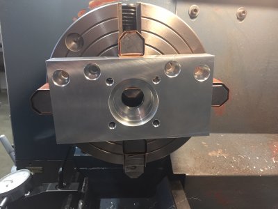
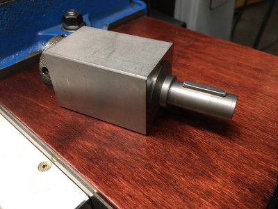
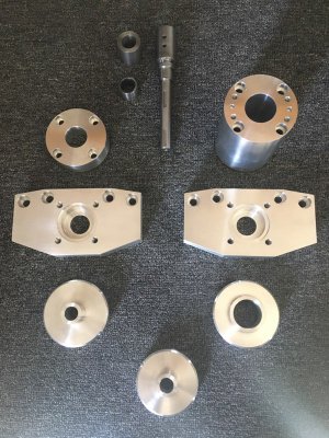
Here's the start of the new bearing blocks. The actual bearing bores were done on the lathe since my mill doesn't have power down feed on the quill. That'll be another modification one day. I added some tapered features to these later on but didn't take any photos of that step.
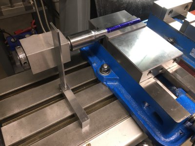
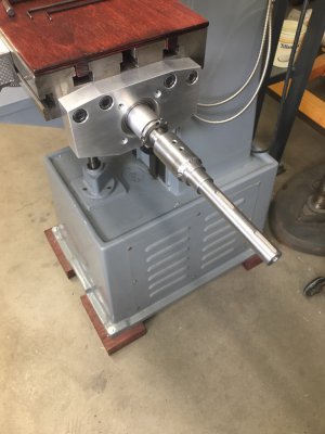
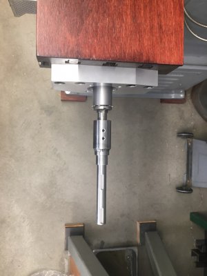
Next the power feed standoff was made. This is to provide clearance so the power feed doesn't strike the one-shot oiler on the side of the knee.
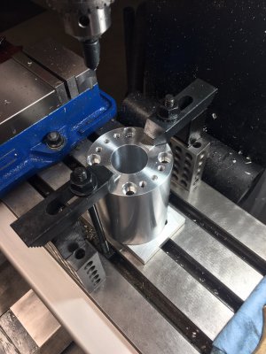
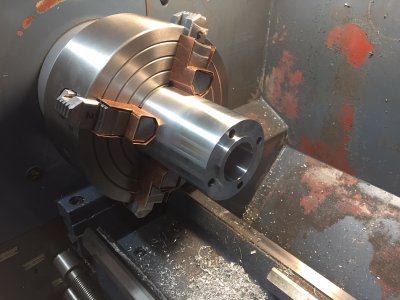
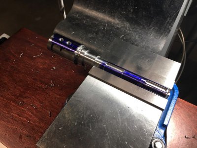
Just a couple shots of that process. The boss shown in the turning picture registers into one of the new bearing blocks.


Here's the start of the new bearing blocks. The actual bearing bores were done on the lathe since my mill doesn't have power down feed on the quill. That'll be another modification one day. I added some tapered features to these later on but didn't take any photos of that step.
Next the power feed standoff was made. This is to provide clearance so the power feed doesn't strike the one-shot oiler on the side of the knee.


Just a couple shots of that process. The boss shown in the turning picture registers into one of the new bearing blocks.
Last edited:


