

- Joined
- Dec 20, 2012
- Messages
- 9,422
A Carriage Stop
(Originally made for an Emco Compact 8 Lathe)

The carriage stop above was made for a good friend who is new to machining but does not own a milling machine so I designed and built it for him. I realize that most guys don’t own an Emco lathe but I think this one is generic enough to hopefully be useful if you need to make one. It’s pretty simple to do.(Originally made for an Emco Compact 8 Lathe)
First, a word about the materials chosen. In my opinion, a carriage stop is not a hard stop or for crash prevention, although it can certainly be used that way. It is more appropriately used as a “soft stop”, a reference that allows you to turn or bore to depth with precision. You power feed until you are close to the stop, then disengage power feed and feed manually until you gently come into contact with the carriage stop. If used this way, a carriage stop can be made from cheap, easily machined aluminum. If you prefer to slam into it under power then use steel or cast iron.
I used a ¼” thick mild steel bar for the clamping plate. It only has to span a short distance, touches the carriage stop and the ways at each end of the bar and is pulled up in the middle by two locking screws so it is more than strong enough for this application. The use of two locking screws allows for a very strong lock to the ways without requiring a lot of torque and I recommend this over a single locking bolt.
Rust is always a concern in Hawaii so I used stainless steel, brass and Delrin for all other components. Since we’re using so little material, costs are low. This stop also uses two zinc-coated springs to combat rust.
Design considerations
I prefer to keep things simple when I can. Carriage stops can have micrometer-adjusted screws, multiple rods in a turret, dial indicators and even micrometer heads incorporated into them. While these configurations can be useful, I have found a simple threaded rod works fine for 99% of the things I use a stop for. If I need to bore or turn a precision step or multi-stage bore I use a dial indicator on a magnetic base to adjust the stop. This is a rare occurrence.
The stop discussed here has springs under each locking screw. This allows me to simply loosen those screws and slip the carriage stop on and off the ways without having to completely disengage the plate from the stop. Everything stays together and nothing gets lost.
The sleeve that holds the stop screw is 303 stainless steel. I chose 303 for its machinability and corrosion resistance. The problem with a long sleeve is tapping it with a standard tap. If you have ever tapped a deep hole in stainless then you know that about half-way in it will feel like the tap is about to snap unless you drill really big; if you do that then the screw will be loose in use and that’s not good. I chose to tap drill the front half of the sleeve and drilled the other half at clearance diameter. Maximum strength on a ¼” screw is obtained in about 1-1/2 times the diameter so 3/8” of thread would be enough for strength; I tapped over double that so the screw is very stable in use.
The sleeve itself is held in a slotted bore by two compression screws with stainless washers under them; it is very solid but to make sure it doesn’t move the sleeve has a shoulder on the saddle side so that it cannot be displaced in use.
I used a Delrin washer under the stop screw locking nut. This allows the nut to tighten really solidly. It also loosens easily but not until you loosen it. Delrin is really good for this sort of thing.
I used brass under the two locking screws. They are big and thick in order to trap the springs and resist the forces of the locking screws. It only takes 1/8 turn to lock each screw and it is a really solid lock.
Finally, I used a nylon cap nut on the end of the stop screw. It is better to have a metal cap or even a bare screw but the Emco Compact 8 does not have a hardened dowel pin at the point of contact on the saddle (yet) so I used nylon for now.
That’s it, nothing special. I used my Sherline mill for this project because I didn’t have a tilting angle table for my larger mill at the time (I do now).
ProcedureThe first thing to do is measure the geometry of the ways with an accurate protractor; I used a Starrett C-493B protractor for this. Most rails will have an upward pointing V-shape with a central flat at the top. Measure the width of the flat, the angle of each leg of the V and the length of each leg. It is useful to make a test template with all your angles drawn out and cut. Then test this template on the front V-way to make sure it all fits as intended.
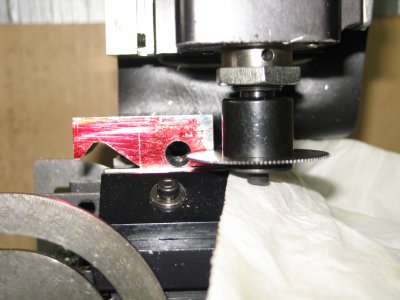
A 1-1/8” H X 1-1/2” W X 2-1/8” L block of 6061-T-6 stock was cut and carefully squared in the mill. One face of the stock was then treated with Red Dykem to provide a layout face.
Next, I drilled two clearance diameter holes for the main locking screws while I could still hold the block securely. These will be ¼-20 socket head cap screws that thread into a locking plate under the stop. Countersinks were cut to house the springs under the locking bolts.


The first cut is the central flat; this defines the inner limit of both angled cuts. That is, when the angled cuts are made the cut is stopped just as it reaches the edge of the central flat. I intended this flat to leave a space of about 1/32” above the ways to prevent the stop from sticking to the ways when it is positioned; a precision fit will cause the stop to drag as you try to move it. Here you can see the 5/32” wide end mill has cut the central flat:


The longer 35 degree angle is cut next. To position the work piece at this angle, a tilting angle table is used and a machine vise is bolted to it. This allows the vise to clamp the work solidly on parallels while allowing the correct angle to be set. The table angle can be set with angle blocks as shown but the protractor on the table itself is pretty accurate as well. Optionally, you can hold the work in your machine vise and prop it up with the angle plates but clamp the plates to the vise. Take light cuts because this arrangement is not as stable as a vise on a tilting angle table.


Note that the end of the cutter is used to cut this flat, and the cut is stopped just as it reaches the left edge of the central flat. The depth of cut is stopped just as the layout line disappears.
The table is then re-set to cut the short angle. This measures 50 degrees but when cutting with the side of the end mill we must use the complimentary angle of 40 degrees (90 degrees – 50 degrees = 40 degrees). The table is set to 40 degrees and the cut is brought to the layout line while also stopping at the edge of the central flat.


The contours that fit the ways have now been cut and this is how it fits:

I then drilled a 10mm hole through the width of the body to accept the stop screw sleeve. The sleeve will be clamped with two socket head cap screws so two holes were drilled with a #17 drill for these screws. I used a 10-32 roll tap to cut the threads. Roll taps form the threads instead of cutting them; they are much stronger than standard taps and the fit they produce is more precise without producing chips.


To finish the machining of the stop, I had to cut 0.040” off the bottom while leaving a ledge 0.1875” wide at the rear of the body. This ledge is at the exact same level as the bottom of the ways. A ¼” thick mild steel plate is used to clamp the stop to the ways. One end of this plate rests on the ledge of the stop and the other end contacts the bottom of the ways. The two ¼-20 locking screws that are located mid-way between these two features pull this plate up, securely locking the stop to the ways.

I neglected to take pictures of the process but I made the brass washers to go under the locking bolts and the Delrin washer to fit the stop screw. The steel locking plate is just ¼” thick mild steel bar with ¼-20 holes for the locking screws.
I made the sleeve from 303 stainless rod. It is just a 10 mm body with a shoulder on one end. It is drilled half-way on the saddle end with a 15/64” drill; the other half is drilled to 9/32”. This allowed me to tap just half the sleeve with a standard ¼-20 tap. The sleeve was slipped into the body of the stop and secured with two 10-32 cap screws. Stainless washers were made to go under these screws.
The stop screw was cut long enough to adjust it by hand and chamfered. A nylon cap nut, Delrin washer and a hardware store knurled nut completed the stop screw assembly.
Two galvanized springs were inserted into the countersinks and the locking bolts and brass washers were installed and threaded into the steel plate under the stop and the carriage stop is complete.


During testing, I locked this stop to the ways with just 1/8 turn on each locking screw and moved the saddle into contact with the stop rod. I then applied what felt like a large amount of force to see if I could get the stop to move but stopped before I stripped the saddle feed gear. The stop didn’t budge at all. Then I loosened the locking screws and was able to lift the stop on and off the ways easily. The stop screw adjusted easily and locked solidly so it all works as intended.
This is a pretty simple project that most hobby guys can easily do. The sequence shown allows your end mill to get in there without anything interfering with the cuts and there are no real critical dimensions, although I would be careful about measuring and laying out your angles.
Cost to me was zero because all of this came out of my current shop supplies. Even if I had to buy the materials the cost would have been pretty reasonable.
Give this a shot if you need a stop, and let me know if there are questions.
Mikey
April 2016, Revised January 2019
")