

- Joined
- Feb 1, 2015
- Messages
- 9,625
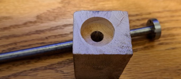
I am in the process of replacing our 110 y.o. railing around our upstairs staircase. I am making new newel posts which will be anchored to the floor with hidden 3/8-16 fasteners threaded into steel floor plates. Here is a cutaway showing the detail. A 1-1/8"horizontal hole is bored to provide access to the mounting bolt and for another 3/8-16 bolt tying a bottom rail to the newel post.

The design requires a 1" internal counterbore in order to clear the horizontal hardware. Obviously, there is no way to use a standard counterbore will work. My solution was to make a removable head for the counterbore and thread it onto an arbor inserted from the bottom.

For material, I used a piece cut from an old leaf spring as it spark tested high enough in carbon to be hardened. I a small piece with my abrasive cutoff wheel and heated it to a dull red and let it cool slowly to soften it. The file test showed it could be machined. I drilled and tapped a 1/4-20 hole which would be the hole for for the arbor but first for a mandrel for machining. Then I roughed out a blank from the piece to minimize turning on the lathe. For a mandrel, I used a piece of 3/8" shafting salvaged from a photocopier. The shaft was mounted in the four jaw and indicated to about .0003" TIR. I turned the end down to 1/4" diameter and single pointed the 1/4-20 thread. With the mandrel still in place, I threaded the blank on and turned to 1.000" diameter and faced both faces.
The counterbore head was created in SolidWorks and exported to SprutCAM to create the G code for machining on my Tormach CNC mill. To mount the part for machining, I clamped my 5C collet chuck in my 4" machining vise. Since the thickness of the part was only .340", I needed a way to ensure that the part was properly oriented in the collet. To that end, I machined a .180" thick x 1.000" i.d. washer for a spacer to seat the part to the proper depth. With the part seated in the collet, the chuck was tightened. I used my edge finder to locate the center of the part. For milling, I used a 1/4" four flute carbide center cutting end mill.
The counterbore is designed to cut the clockwise rotation of the tool so that the cutting forces will tighten the counterbore on the shaft, eliminating the need for a locking mechanism. This causes an issue in that the counterbore has to be disassembled in situ in order to remove it. I decided to add two 1/8" holes to permit use of a spanner wrench to enable removal. The holes were drilled on a 3/4" bolt circle.
I didn't add the side cutting edges in my model as there was no practical way to hold the part for that machining. Had I not scrounged the material, I would have used bar stock and left it long to allow work holding, parting it off as a final operation. I also could have mounted the part in the 4th axis RT and machined the edges that way but it have relied on the 1/4" thread for work holding which I felt was not sufficient for machining a high carbon steel and I would have had to set up the 4th axis. so I decided to just turn some relief on the circumference.
For the spanner wrench, I used a length of 1/2" hot rolled and drilled two 1/8" holes 3/4" apart. For the pins, I have a collection of broken pc drills. The shanks are a medium carbon steel and well suited for the need. I pressed the pins in and purtied up the wrench a little. It's less likely to get thrown away that way.
I filed the cutting edge relief by hand and touched it up with a diamond hone. I tried a cutting a test piece and it did a superb job. Actually, better than I could do with my Forstner bits. I had intended to harden it but since it will only be used for two cuts, decided to leave it unhardened. If I notice the edge dulling, I can harden it then.
This is the completed counterbore head. There are some artifacts from filing the relief in back of the trailing edges. The two holes are for removing the head in situ after cutting the counterbore

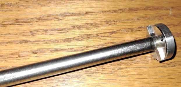
Here is the assembled counter counterbore. There is a small piece where the raw saw cut didn't clean up. Ir would have been if I had cut the relief on the circumference but I decided to leave it as is. Engineering change
The last photo shows the counterbore, the spanner for removing the head, and a test on a piece of scrap.

Thinking about it, I could have simplified the tool by eliminating the central boss. That would have made it possible to make with a manual mill. When I originally designed the counterbore, I didn't know how thick candidate for material would be so I decided to leave the boss. As it turned out, the spring was thick enough for that modification to have worked.
As with many of my tool projects, it takes hours to make the tool and seconds to actually use the tool.At least in this case, there was no commercial alternative.
Actually, I remembered that years ago I had a Craftsman router bit with a removable arbor. The dado head that I had was only 3/4" but I did a search and found that the arbors still exist and I could have purchased a 1" dado head threaded for 1/4-28 L.H. It looked like I could have reversed the arbor and run it in reverse. The cost was $21 plus shipping but true to HM tradition, why buy when you can make? It's what we do.
The design requires a 1" internal counterbore in order to clear the horizontal hardware. Obviously, there is no way to use a standard counterbore will work. My solution was to make a removable head for the counterbore and thread it onto an arbor inserted from the bottom.
For material, I used a piece cut from an old leaf spring as it spark tested high enough in carbon to be hardened. I a small piece with my abrasive cutoff wheel and heated it to a dull red and let it cool slowly to soften it. The file test showed it could be machined. I drilled and tapped a 1/4-20 hole which would be the hole for for the arbor but first for a mandrel for machining. Then I roughed out a blank from the piece to minimize turning on the lathe. For a mandrel, I used a piece of 3/8" shafting salvaged from a photocopier. The shaft was mounted in the four jaw and indicated to about .0003" TIR. I turned the end down to 1/4" diameter and single pointed the 1/4-20 thread. With the mandrel still in place, I threaded the blank on and turned to 1.000" diameter and faced both faces.
The counterbore head was created in SolidWorks and exported to SprutCAM to create the G code for machining on my Tormach CNC mill. To mount the part for machining, I clamped my 5C collet chuck in my 4" machining vise. Since the thickness of the part was only .340", I needed a way to ensure that the part was properly oriented in the collet. To that end, I machined a .180" thick x 1.000" i.d. washer for a spacer to seat the part to the proper depth. With the part seated in the collet, the chuck was tightened. I used my edge finder to locate the center of the part. For milling, I used a 1/4" four flute carbide center cutting end mill.
The counterbore is designed to cut the clockwise rotation of the tool so that the cutting forces will tighten the counterbore on the shaft, eliminating the need for a locking mechanism. This causes an issue in that the counterbore has to be disassembled in situ in order to remove it. I decided to add two 1/8" holes to permit use of a spanner wrench to enable removal. The holes were drilled on a 3/4" bolt circle.
I didn't add the side cutting edges in my model as there was no practical way to hold the part for that machining. Had I not scrounged the material, I would have used bar stock and left it long to allow work holding, parting it off as a final operation. I also could have mounted the part in the 4th axis RT and machined the edges that way but it have relied on the 1/4" thread for work holding which I felt was not sufficient for machining a high carbon steel and I would have had to set up the 4th axis. so I decided to just turn some relief on the circumference.
For the spanner wrench, I used a length of 1/2" hot rolled and drilled two 1/8" holes 3/4" apart. For the pins, I have a collection of broken pc drills. The shanks are a medium carbon steel and well suited for the need. I pressed the pins in and purtied up the wrench a little. It's less likely to get thrown away that way.
I filed the cutting edge relief by hand and touched it up with a diamond hone. I tried a cutting a test piece and it did a superb job. Actually, better than I could do with my Forstner bits. I had intended to harden it but since it will only be used for two cuts, decided to leave it unhardened. If I notice the edge dulling, I can harden it then.
This is the completed counterbore head. There are some artifacts from filing the relief in back of the trailing edges. The two holes are for removing the head in situ after cutting the counterbore
Here is the assembled counter counterbore. There is a small piece where the raw saw cut didn't clean up. Ir would have been if I had cut the relief on the circumference but I decided to leave it as is. Engineering change
The last photo shows the counterbore, the spanner for removing the head, and a test on a piece of scrap.
Thinking about it, I could have simplified the tool by eliminating the central boss. That would have made it possible to make with a manual mill. When I originally designed the counterbore, I didn't know how thick candidate for material would be so I decided to leave the boss. As it turned out, the spring was thick enough for that modification to have worked.
As with many of my tool projects, it takes hours to make the tool and seconds to actually use the tool.
Actually, I remembered that years ago I had a Craftsman router bit with a removable arbor. The dado head that I had was only 3/4" but I did a search and found that the arbors still exist and I could have purchased a 1" dado head threaded for 1/4-28 L.H. It looked like I could have reversed the arbor and run it in reverse. The cost was $21 plus shipping but true to HM tradition, why buy when you can make? It's what we do.
")