A couple of questions about a lathe motor swap

luxige

Registered
Registered
Joined
Apr 4, 2019
Messages
113
I bought an older used German-made lathe, which I’ll post about in detail later. But first, a few quick questions about motor wiring.

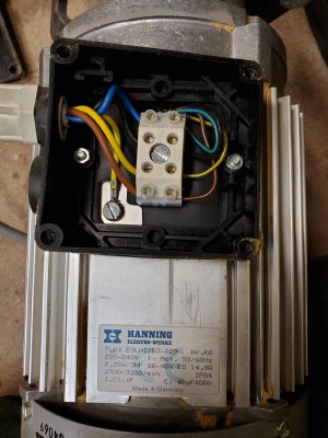
The lathe came with a 440/550V motor driven by a 3ph VFD. I’ll be selling those and putting in a nice, nearly new 3hp 220V 1ph Hanning motor I happen to have sitting around. I’ve included a picture of the junction box which unfortunately doesn’t include a wiring diagram. I also can’t find one on the Hanning website. So I’m *guessing* I should connect the Yellow and Blue to one line with Black and Brown to the other line, for (say) Forward. And swap the Blue and Brown connections to get Reverse. So:

Forward = Line1 —> Yel + Blu / Line2 —> Blk + Brn
Reverse = Line1 —> Yel + Brn / Line2 —> Blk + Blu

Question 1: Would it be safe to bench test those configurations, or could I damage the motor if I guessed wrong about the pairs?

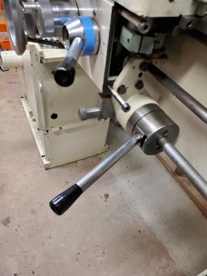
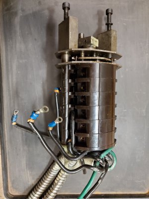
The second issue is about the motor control switch. The shop that had this lathe set up a push button panel and disconnected the original switch. For some reason they didn’t discard it, so I still have the control lever and big modular rotary switch. See pictures. The lever has a lock when at center position (all 12 switches open), so that’s “OFF.” Then there are two detents above and two detents below. So I can have Forward/Reverse with and without the coolant pump. (I have a 230V eighth hp motor to replace the 550V one in the pump).

Question 2: Obviously the gear was designed to handle this duty, but is it okay by today’s safety standards? I will add a contactor and E-Stop/Start buttons to shut down line power if needed.

Thanks in advance for your advice.
 

Attachments

  • 20200415_002720.jpg
    20200415_002720.jpg
    1.6 MB · Views: 15
  • 20200415_120833.jpg
    20200415_120833.jpg
    1.7 MB · Views: 18
  • 20200415_120956.jpg
    20200415_120956.jpg
    1.5 MB · Views: 18
If you just momentarily "bump" the motor on a bench test, you will not hurt it, and the rotary switch is OK alone, as long as there is a fuse or breaker in line ahead of it, I have a two speed motor on my 19" lathe, and that is how it has been for 40 years without any problem, it uses a rotary two stage set of contacts for both forward and reverse.
 
I have some diagrams below that could help. The mechanical system is up to the task though the electrical unit is not necessarily up to the amperage as you are reducing the voltage. So use sufficiently heavy gauge wires that that are to the rated heat, amperage and voltage.
The Grizzly T24101 is sufficiently large enough for the current and can be used as the safety disconnect and thermal overload. The long yellow line on the right of the grizzly diagram can be spliced then lead to an emergence stop box else where on the machine, continuity when puled out and discontinuity when pressed. Be sure to add a ground line to the Estop box even though is seams useless in adition to gronding the motor, as it will safely trip the breaker if the cable is spliced or filed with water. The diagram of three circuits is for the drum switch. be sure to get a drum switch of 25 amps.
1587000193305.png
1587000250402.png
1587000293072.png
 
If you just momentarily "bump" the motor on a bench test, you will not hurt it, and the rotary switch is OK alone, as long as there is a fuse or breaker in line ahead of it, I have a two speed motor on my 19" lathe, and that is how it has been for 40 years without any problem, it uses a rotary two stage set of contacts for both forward and reverse.

Thank you, Ben!
 
I have some diagrams below that could help. The mechanical system is up to the task though the electrical unit is not necessarily up to the amperage as you are reducing the voltage. So use sufficiently heavy gauge wires that that are to the rated heat, amperage and voltage.
The Grizzly T24101 is sufficiently large enough for the current and can be used as the safety disconnect and thermal overload. The long yellow line on the right of the grizzly diagram can be spliced then lead to an emergence stop box else where on the machine, continuity when puled out and discontinuity when pressed. Be sure to add a ground line to the Estop box even though is seams useless in adition to gronding the motor, as it will safely trip the breaker if the cable is spliced or filed with water. The diagram of three circuits is for the drum switch. be sure to get a drum switch of 25 amps.
View attachment 321125
View attachment 321126
View attachment 321127

Thanks Alexander, that's all very helpful! I have mapped the drum switch contacts and came up with about the same thing, with switching for the pump as well. Good to see some confirmation though.
That Grizzly unit looks perfect, so I think I'll just go with that. Thanks again.
 
Just noticed a mistake in the above circuit. I checked it for short circuit risk but nut for function. The leads to the starter winding weren't staggered enough, see below.
1587045650034.png
 
I wonder if your Hanning motor has an internal capacitor or needs to have an external one provided?- I see 40uF on the nameplate.
Secondly, the rotary switch should be "rung out" with a continuity tester to verify the internal contact arrangement if you plan to use it
-Mark
 
As a separate issue, giving the very high voltage and being 3-phase, it makes me think that the original motor was probably at least 5hp. If so, are you okay with the 80% reduction in potential torque?
 
I wonder if your Hanning motor has an internal capacitor or needs to have an external one provided?- I see 40uF on the nameplate.
Secondly, the rotary switch should be "rung out" with a continuity tester to verify the internal contact arrangement if you plan to use it
-Mark

Good points Mark. I'm hoping the cap/s are mounted inside with the centrifugal switch. This was pulled from a multifunction woodworking machine with three of these motors. Worst case: the motors share one set of caps and I'll have to source new ones and figure out how to wire them in.
"Rung out" - always good to learn new lingo! I have done that. I'll be using three of the six modules. I don't think I'll be adding any auxiliary equipment, but I'll leave the other three modules stacked on there just in case.
 
Back
Top