A couple of questions about a lathe motor swap

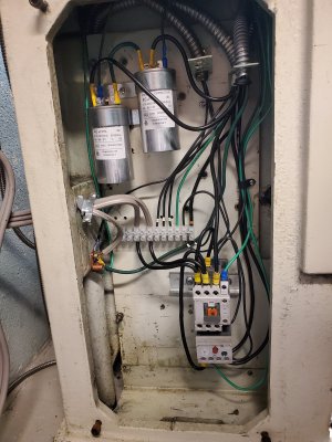
The cap you ordered should work fine
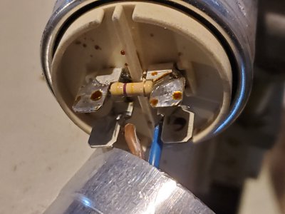
"ringing out" is a term from even before my time; it refers to testing a motor or generator armature on a fixture that buzzes when there is a shorted
segment on the commutator- I think
:)

Thanks for the input!
 
One more new wrinkle...
I found the user manual for the woodworking machine, which I didn't even know I had. It has wiring diagrams, unfortunately they are only a little bit like reality. But they do show 100k resistors in parallel with the capacitors. I removed the end cover from one of the capacitors and there's the resistor. See photo. Bands look like tan, brown, yellow. Which makes no sense. Then I realized maybe they faded from brown, black, yellow = 100k. They are about 9mm long and 3.2mm diameter, which would be .5W. Ordered some.

In related news, I have mapped the wiring of the contactor/overload, selector switch, start & stop switches, and capacitors as installed in the original machine. My head hurts now.
 

Attachments

  • 20200417_141207.jpg
    20200417_141207.jpg
    2.8 MB · Views: 9
Last edited:
That is a bleed resistor, it takes a little bit of power away from the motor when running, though it makes the whole thing safe for when being serviced. It bleeds off the capacitor's energy hopefully before you get your hands in there. Just a quick calculation, if there is 400volts across that capacitor, then there is 1.6 watts needing to be dissipated for the first moment. That of course quickly drops off so over a the dissipation duration, the engineers probably said that a half watt was good enough not to over heat. Though that concerns me that they were sparing with cost that they couldn't put a 2w resistor in there.
 
Thanks for the expanation. I'm learning as I go, and all this helps.
To clarify, the machine this motor is coming from is 220V. So 0.5W seems correct, yes?
 
Yes but this is ac so there are peaks that are higher-220 is the RMS or average value of the voltage
100 k was chosen so the cap would bleed off fast- you could put a higher value in there like 500k and just wait a few seconds longer before servicing the caps
Most motors don't have a bleed resistor but it is a good idea
-m
 
Success! The motor runs and reverses. The big rotary switch controls the direction and also runs the coolant pump when moved to the high speed position. (The original 440V setup had two speeds in each direction). My new motor only runs at one speed so I'm using the extra switch positions to control the coolant pump. I replaced the 550V 3ph stock pump motor with a 230V 1ph 1/8 hp motor I happened to have laying around. I added an old Start/Stop switch and E-stop switch to control a contactor and overload cutout similar to the one recommended in post #3.
Everything is working, however.…

Now I’m thinking about adding a centrifugal switch to cut out the start cap. The other machine uses a momentary switch to start, and I’d rather just use the shift lever without also having to push a start button.

An odd thing: it seems I won't need to worry about that centrifugal switch. (When the control lever is in neutral, all motor and capacitor leads are isolated. Moving it to a run position energizes the appropriate motor leads and the Run cap. The Start cap can only be connected by pressing the Start button, as this is the only way I could figure out how to keep it from always being on without a centrifugal switch to cut it out.)
So I was expecting to have to hit the Start button each time I moved the control lever to a new position.
But! The motor starts anyway, as soon as the control lever is set. ??? My first thought was that I had wired the Start cap wrong and it was always getting power. I triple checked my plan and also tested for continuity between power leads and cap leads. No mistake, that motor is starting without the Start cap.

So.… any problem starting the motor that way? I don't want to do damage just because it's convenient.
 

Attachments

  • 20200424_231431.jpg
    20200424_231431.jpg
    2.1 MB · Views: 6
Back
Top