A Question of Runout

The spindle runout is 0.0005", so pretty low but not your typical which is around 0.0001" on better lathes. The runout on the ER chuck internal mating surface was 0.003" and 0.0045" when flipped 180 degrees. Also the nut and the seating of the ER collet can have an effect on TIR. Kind of guest work on the effect of the runout of the spindle mounting on the ER collet chuck as you would need to clock the collet at different points in the spindle, not just 180 degrees and assume one is the null and the other is the max. There are also many factors as to the chuck mount and the drawbar system as opposed to just tapping it into position (i.e. the MT surfaces may not be a perfect match and surface irregularities) It is not uncommon on mounting chucks to clock them on the spindle for minimum runout and then use an index mark in the future for mounting. To give you an example I have a Jacobs chuck with a JT mount to an R-8 collet mount. I indexed the collet in a 4J chuck for 0 TIR and then used a ground pin in the chuck and clocked it for minimum runout and then marked and locked the two together. Spindle runout on my mill is under 0.0001" so this is not a factor and it was a high quality R-8 collet, The null TIR on the 14N chuck is around 0.0004" and fairly consistent. The worse case before clocking was around 0.0011". Good enough for this type of chuck.
20160103_143521.jpg

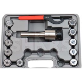
As far as ER chucks I have both ER-32 R-8 and ER-40 MT3 and the mating surfaces are around 0.0002" mounted, so the Banggood ER chuck is horrible. The other significant factor is that my guess is that he has a metric 1 mm ER increment set. So say you try to mount a 1/2 rod in a 13mm collet and collapse it down, the runout gets much worse at the clamping extremes, and not all ER collets are created equal. Based on my own experience with much better quality ER chucks and collets, you want a set of collets to match what you are holding imperial vs. metric. The quality/type of collet nut can also make a big difference. I use an ER-32 collet setup in my mill to setup my edge finders, the runout of my 12 mm collet mounted is 0.0002" (which is much better than my R-8. The edge finder resolution is 0.0004" so the runout of the collet system is a critical factor to get everything setup.
 
In doing more research I came across a second video by the same guy in which he did mark the spindle high points and did some more detailed analysis. I guess I wasn't the only one that was confused. This is a 35 minute vid and I scanned it but haven't had the time to to watch it beginning to end yet.

 
Another issue to consider is angular runout. The Morse taper socket centerline may be at an angle to the spindle axis. If so, the test indicator may show zero runout within the bore but extended outward into the real world, the there may be a significantly higher runout.
Runout had to be parsed out into radial runout and angular runout. It can be assessed by making tow readings within the bore as for apart as possible. If both are zero all is good. However, with non-zero readings,, is is necessary to look at the clock position as well as the value. If both have the same reading at the same clock position, there is no angular runout, only radial.

The following illustrates the four runout conditions that can exist between two entities.
Case A shows zero runout; the MT4 axis is coincident with the spindle axis. No matter where along the spindle axis a measurement is made, there will always be zero runout.
Case B shows a radial offset. The MR4 axis is parallel to the spindle axis. No matter where along the spindle axis a measurement is made, the runout measurement will be the same.
Case C shows an angular offset but at some point along the spindle axis and the MT4 axis intersect and the composite runout will be zero at that point but at no other.
Case D shows a radial and an angular offset. At no point along the spindle axis do the two axes intersect. There will always be a non-zero runout measurement. However, the two clock positions will either be the same or 180º apart, depending on whether the intersect poin it ourside or between the two measurement positions.There will be two perpendicular planes containing the MT4 axis such that one plane is parallel to the spindle axis and the second plane intesects the spindle axis.

In both Case C and D, the further away from the intersection point we get, the worse the composite runout is. In the real world Case D always exists. There is never a perfect Case A situation. However there can be a "good enough"situation.
Runout Cases.JPG

So how do we assess the situation? Both radial and angular runout have to be measured for each component. This means making two measurement as far apart as possible along the axis. Done accurately, some device capable of measuring rotational angle would be used. The device would have to have a center previously shown to have zero runout. For most purposes though, it would probably suffice to mark an index line on the test piece and note the clock position for the maximum runout condition. Checking a spindle socket, I would make two measurements a known distance apart. Remember that the TIR measurement is actually twice deviation. The positions can be manipulated with some trigonometry (polar coordinates will help) or the points can be plotted in a 3D cad system. Once this is done, it is possible to predict the runout at any given point along the spindle axis.

In stacking multiple adapters, the possible combinations starts to grow and the ability to parse out the contribution of any given component becomes more difficult. Consider the ER32 chuck. Runout can exist in the MT socket, the ER socket and nut, the ER collet, or a rest pin mounted in the collet. It is virtually impossible to assess runout by making a measurement or two of runout on a pin mounted in a collet.

A better approach would be to measure each using test centers. Knowing the contribution of each component, it would be possible to orient the assembly for a minimum aggregate runout.
 
This is a follow-up video I just ran into regarding the poor TIR of the one of these Chinese ER-32 chuck/collet sets that he tried to regrind the chuck. The TIR is a cumulative factor of all the components, and there always will be a range depending on how they all stack up/indexed. This particular chuck/collet package has pretty dismal quality, regrinding the chuck did not improve the results because the collets were no better. At the end of the day, the whole setup was a toss.
 
My ER32 collet set arrived. I'm been taking TIR measurements ever since. I'm getting dizzy!
HF 33686 Mill Drill
Spindle bore .0005"
R8 collet w/5/16 pin .0015"
R8 collet w/1/2" pin .0001" ???
R8 RE32 chuck bore .0022"
R8 ER32 chuck face .003 w/rough spot to .005"
R8 ER32 collet w/5/16 pin .003/.004"
R8 ER32 w/ 3/8" pin .003"
I have 3 questions;
1. How bad are the numbers above?
2. Can the rough spot in the collet chuck face cause runout?
3. The top end of the drawbar rattles around in the spindle bore with about 1/8" clearance . Will making a bushing to tighten that up reduce runout?
Thanks for any help.
With those numbers by the time you drill a hole or use an endmill error is substantial (more than I could live with).
for example: say you want to slip fit a dowel in a hole,you could oversize .0015" to get a clearance fit( assuming the hole is fairly cylindrical, another issue).
That is why you need the low TIR numbers.
 
The numbers are about 10X worse then a better quality set, so for example the Shar's set specifies less than 0.0002" concentricity of their chucks and 0.0003" on their collets. Typical is something in the 0.0002-0.0003" of collet and chuck would be expected. This assumes your spindle is also concentric. Will it make a difference in your HF 33686 Mill Drill, probably not in most cases. Still, pretty poor numbers and I would not want to use them for any close tolerance work, would not use them to hold stock in a lathe. If the collet surface is irregular this will effect the clamping and may introduce worse skewing. The issue of axial skew can be a significant issue with chucks/collets, so you may measure a TIR of say 0.003" at one point and then move out 3-4" and find you are at 0.012". This can be a significant issue with poor performing chucks and collets. I have the Shar's ER40 MT3 and R8 chucks and the runout meets specification. These are their nickle plated versions and are quite decent for the price.
As far as the upper bushing of the drawbar it will have no effect on the TIR, but it is common for it to be undersized. Many of us have made close tolerance bushings to decrease the rattle of the drawbar.
 
With those numbers by the time you drill a hole or use an endmill error is substantial (more than I could live with).
for example: say you want to slip fit a dowel in a hole,you could oversize .0015" to get a clearance fit( assuming the hole is fairly cylindrical, another issue).
That is why you need the low TIR numbers.
The numbers are about 10X worse then a better quality set, so for example the Shar's set specifies less than 0.0002" concentricity of their chucks and 0.0003" on their collets. Typical is something in the 0.0002-0.0003" of collet and chuck would be expected. This assumes your spindle is also concentric. Will it make a difference in your HF 33686 Mill Drill, probably not in most cases. Still, pretty poor numbers and I would not want to use them for any close tolerance work, would not use them to hold stock in a lathe. If the collet surface is irregular this will effect the clamping and may introduce worse skewing. The issue of axial skew can be a significant issue with chucks/collets, so you may measure a TIR of say 0.003" at one point and then move out 3-4" and find you are at 0.012". This can be a significant issue with poor performing chucks and collets. I have the Shar's ER40 MT3 and R8 chucks and the runout meets specification. These are their nickle plated versions and are quite decent for the price.
As far as the upper bushing of the drawbar it will have no effect on the TIR, but it is common for it to be undersized. Many of us have made close tolerance bushings to decrease the rattle of the drawbar.
Thx for the links. These collets will only be used in my mill. My mill spindle bore has .0005" TIR. As the inside bore of my R8 ER32 collet chuck has .0022" TIR it seems I can get a substantial improvement with a better quality ER32 chuck. I was checking out the SHARS ER32 R8 chuck in the link you provided. In the product bulletin it say the face has .0002" runout. On the catalog page it says .0002" concentricity ID to OD. I'm not sure what these terms mean or if they're interchangeable. My collet chuck bore reads .0022 on the inside surface.
 
As the inside bore of my R8 ER32 collet chuck has .0022" TIR it seems I can get a substantial improvement with a better quality ER32 chuck.

Are you sure you're measuring the right thing? My understanding is that an ER collet chuck depends more (well, in the range we're taliing about I mean) on concentricity of the nut than the chuck itself - and the nut is difficult to measure due to the eccentric ring inside. The only runout that should matter for the collet chuck itself would be the shaft that mates with the spindle.
 
Are you sure you're measuring the right thing? My understanding is that an ER collet chuck depends more (well, in the range we're taliing about I mean) on concentricity of the nut than the chuck itself - and the nut is difficult to measure due to the eccentric ring inside. The only runout that should matter for the collet chuck itself would be the shaft that mates with the spindle.
No I can't say I'm sure about what causes runout but it seems to me If the taper in the chuck bore is running out over 2 thousandths the collet can't be any better than that. Now my mill spindle has 5 tenths of TIR but as I can't clock the collet chuck because of the key way the TIR is what it is. I don't know if the spindle runout is adding to the ER32 chuck runout, or subtracting from it, or anything in between. Having over .002 TIR in a collet chuck seems to defeat the purpose of using a collet.
 
Back
Top