A small part of a big project

cjtoombs

Active User
Registered
Joined
May 10, 2012
Messages
995
I decided some time ago that I wanted an RV of some sort. After some thought, I decided on a truck camper. There is a small problem, though. Truck campers (and specifically the one I bought) look something like this:
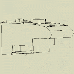
Lance 1161 Bottom Layout.GIF

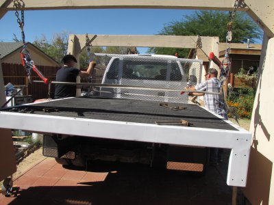
And my truck looks like this:
IMG_2815.JPG
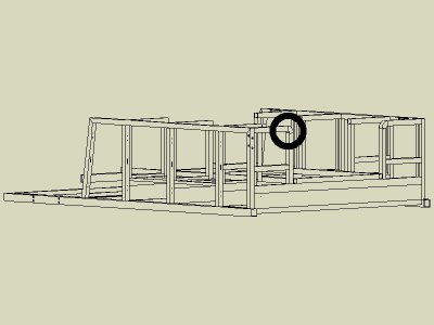
Which called for a solution, the one I came up with will look like this when it's done:
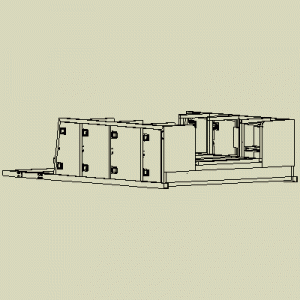
Lance 1161 Bottom Layout 01.GIF
This subframe will allow the camper to go all the way to the front of the 10 ft bed, as well as supporting and attaching the camper to the bed through the stake pockets. It also provides quite a bit more storage where the wheel well holes are on the camper. More to follow, wife wants me to go somewhere now.

Lance 1161 Bottom Layout.GIF IMG_2815.JPG Lance 1161 Bottom Layout 01.GIF
 
Ok, can't add any more pictures, says I have exceeded my quota by 73 mB, so I will continue this at some later date, when I can post pictures again.
 
You have enough posts. There should be no limit on you. Let me check?

"Billy G"
 
Test message:

IMG_3578.JPGIMG_3578.JPGIMG_3578.JPGTHM_Large.gif


I just uploaded this stuff under his account with no issue.

Nels

IMG_3578.JPG THM_Large.gif
 
The problem has been fixed. You are no longer limited. Have fun.

"Billy G"
 
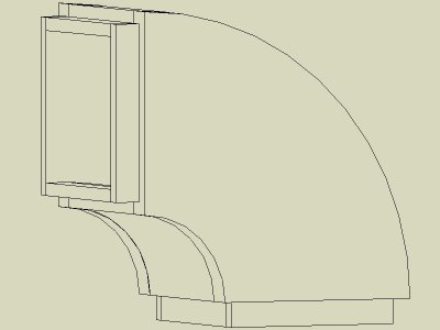
Thanks, gents, for getting me going again. Now, on with the story. The part that I will be focusing on in this thread is this one:
Lance 1161 Bottom Layout 02.JPG

A bit closer look at it:

Lance 1161 Bottom Layout 03.JPG

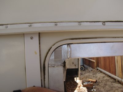
The camper has a radius (sort of, it's not very accurate) at the front (not shown in the model of the camper) and this part is designed to match it, as well as possible.

Lance 1161 Bottom Layout 02.JPG Lance 1161 Bottom Layout 03.JPG
 
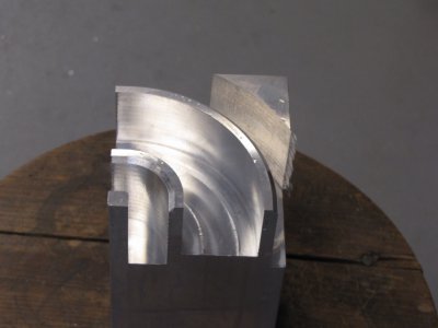
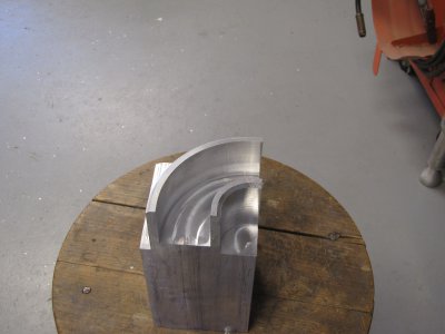
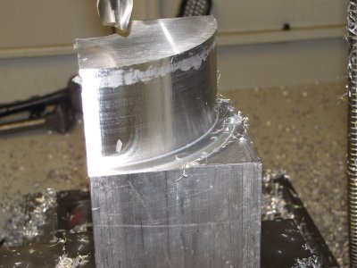
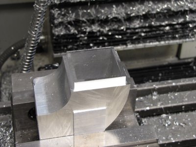
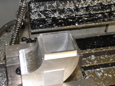
With the background out of the way, lets get down to cutting some metal. The models that I showed in the earlier posts were done in Turbocad, and I used the Turbocad CAM plugin to generate some G code and put a 3.5" square bar of 6061 in the vise and cut this out:

IMG_3694.JPG

The outside dimensions are .030 large at this point. I removed the nubs on my Craftsman 3 wheel bandsaw (I used a slitting saw on the second one, my bandsaw was out of commission at the time, and holding this thing at an angle to cut it off wasn't easy, or recomended):

IMG_3695.JPG

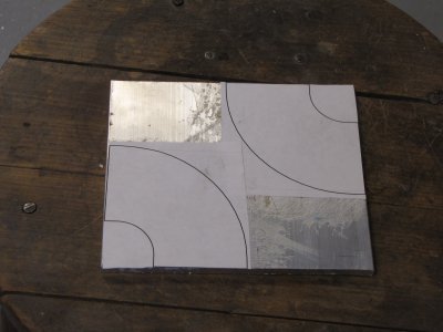
I laid out the tops by printing the shapes out from Turbocad and gluing them to the plate:

IMG_3696.JPG

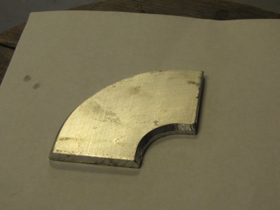
This was cut out on the bandsaw (luckily I did both of the before the saw crapped out). The bevel was filed on the outside with a body file, inside with a course rat tail file.

IMG_3698.JPG

IMG_3694.JPG IMG_3695.JPG IMG_3696.JPG IMG_3698.JPG
 
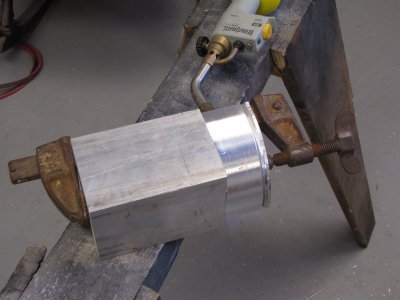
The bevels on both parts are to help with weld penetration. Here the parts are clamped up and ready to weld:

IMG_3699.JPG

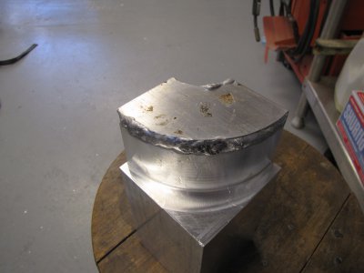
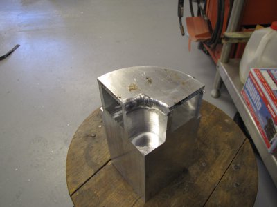
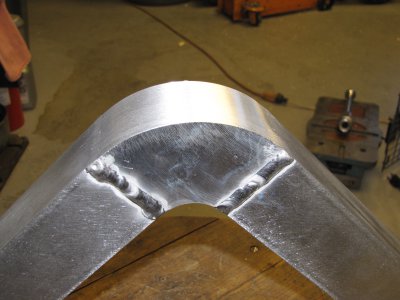
I preheated the part for a while with the torch, since I only have 200 amps to work with, and I didn't want that big chunk of aluminum sucking up all my heat. Here is the welded part. This is my first big project welding aluminum, I am improving, but don't claim perfection on these welds :)

IMG_3700.JPGIMG_3701.JPG

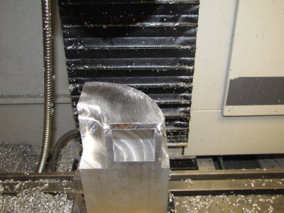
This was set up in the machine. Since I indicated to the corner vise jaw to begin with, I just made sure it was flush to the right side of the vise jaw, and it was back in the position it was cut in the first time.

IMG_3702.JPGIMG_3705.JPGIMG_3706.JPG

This is where that .030 I left on the outside earlier came off. I used a slitting saw to get through most of the parting (it wasn't large enough to do the whole thing) and used the bandsaw to complete it. The second one had to be hacksawed off, since the bandsaw wasn't working.
IMG_3707.JPGIMG_3708.JPG

IMG_3699.JPG IMG_3700.JPG IMG_3701.JPG IMG_3702.JPG IMG_3705.JPG IMG_3706.JPG IMG_3707.JPG IMG_3708.JPG
 
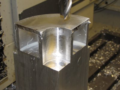
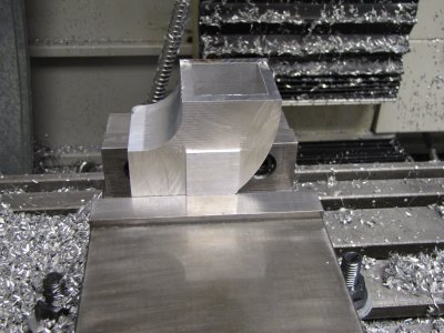
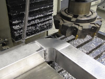
I'd like to say I planned it this way, but that square nub that was left on came in handy in the next setups. I used it to ensure that the ends to be cut were square with the spindle on the machine:

IMG_3709.JPG

Then I cut the relief so that the 1/8" thick 2" tube would slip over it:

IMG_3711.JPG

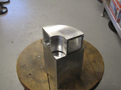
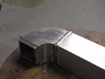
After cutting the other relief this was welded to the tubing:.

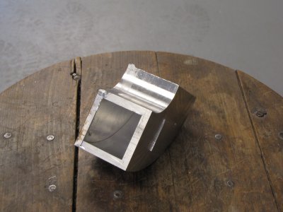
IMG_3713.JPGIMG_3714.JPG

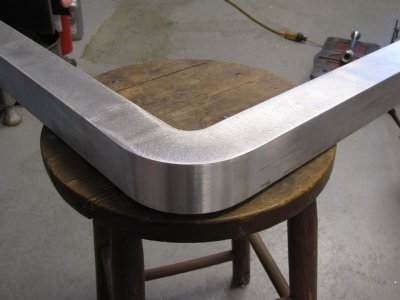
The welds on the sides were cut down flush and smoothed off, as well as on the outside of the radius. The inside of the radius was left as welded, as nothing attaches or contacts it:

IMG_3719.JPGIMG_3722.JPG

This is where it will actually be on the camper:

IMG_3716.JPG

It's pretty close, but the camper isn't a perfect radius. Some sealer will take care of the rest. I'm probably overbuilding this subframe, but the old engineering saying "when in doubt, build it stout comes into play here. I was originally going to build it from steel, since the welding would have been much easier, but the weight was going to be way over what the camper jacks would handle, so I opted for aluminum for the entire structure. So far I have the sides done and two of the support I beams done, as well as these two parts. I have 3 more I beams to go, then I can start welding parts together. I will either have to attach them to the camper or build a jig to ensure that the hold down bolt on the camper align with the features on the frame they bolt to. Once that is done, then there are internal items (drawers, shelves) to be done, then skinning the bottom and front, then the doors. I'll probably post more on the doors, since they are pretty complicated, but I won't be doing them for some time.

IMG_3709.JPG IMG_3712.JPG IMG_3711.JPG IMG_3713.JPG IMG_3714.JPG IMG_3719.JPG IMG_3722.JPG IMG_3716.JPG
 
I have thoughts of doing projects such as this but at this moment in time I lack the talent. Very nice!!
 
Back
Top