About welding RF ignition arc-start

On Topic and Off. High Freq has been around for years. I had it 30 + yeras ago in my truck shop for stick welding. A Century AC-DC welder with add-on High Freq box. I used it for welding on farmers' S--t spredding tractors. Tractors that only scrapped the holding lots while the cows waited to be milked. As you can expect, there was not a lot of clean metal on the machines and implements. I burned 6011 or 6013 rods as best I could on patches and repairs. Sometimes I couldn't get them started. The high freq was a godsend UNTIL one day in the summer. It was 100 degrees with 100 percent humidity and I was soaking wet. Crawled under a John Deere to repair a blade and that *&*$# high freq traveled down my gloves and clothes and LIT ME UP!! Never turned it on again. No problem with it for TIG or using it under controlled circumstances. But if you are thinking about using in general, beware.
 
You can TIG weld aluminum with DC current, NASA and the aerospace industry (because of weld quality) does it all the time, using AC is easier and more forgiving, why almost everyone else uses it.
 
From what I am finding, there are some (very) homebrew solutions, usually involving one of those cheap little high voltage generators from eBay, and a spark plug to make low frequency splat sparks. Activated with a foot switch. Unsurprisingly, a high voltage "spark" will disrupt the TIG main inverter control circuitry, and that protagonist avoided the direct connection by having another spark gap in the handle, which by then sports an add-on wire.
This, of course, is all very crude, but it confirms the principle I was trying to get articulated.

I value what @Mitch Alsup was saying. @Chewy experienced a spark-plug style shock from a very crude kind of spark starter. Not the same as true RF. There is irony here about needing the electronics degree. :)

The property of HF voltages, by which I mean a (RF) Radio Frequency alternating high voltage is that you do not get any shocks. It is a different circuit to the common electronic ignition sparks maker. To be sure, you can get burns from the hot ionized air, but the RF current travels mostly over you than through. The guys who have played with Tesla coils (including me) can attest that it is easy to place one's hand on 60,000Volts of 500kHz RF, while holding a screwdriver, and see foot-long sparks and corona leaping from the thing while one's hair steadily rises and spreads out. I used to check if a 10kW transmitter for 300kHz ADF air navigation was switched on by touching a 9mm screwdriver to the antenna connection outside the building, and drawing away about 6" of reddish noisy arc. My hand would be firmly gripping the screwdriver shaft, so that only the end of the screwdriver suffered the hot air. That RF current was using my body as the counterpoise to the antenna, still transmitting. One does not feel anything unusual, and I have lived the greater part of my life since.

WARNING: These Tesla coil things are deadly if not operated with care - not from the high voltage, but instead from the "low" voltage 240V AC power cables. Those who know carefully have them battery operated, and taken out well away from anything with a power line, including street lamps. A RF arc is a ionized gas almost zero ohms conductor. The plasma, finding a mains line, connects you to it as if it had the wire stripped and wrapped around your ankle. DO NOT !!! AC mains electric shock kills. 60kV of 500kHz RF does not.

That all said, (with disclaimer), the principle seems straightforward. The cost of add-on parts in home-brew style HF-Start project seems to be about $30 - $40, plus about 3 weekends.

This does not mean I am advocating using these. There is perhaps a sound reason why they are not on every welder by now. Only - I have not seen it convincingly spelled out yet. Sure the whole world welds. I am just after removing the mystery to the point I understand it, right down to the on/off switch.
 
It seems the feature required by inverter-type TIG supplies is a low-pass filter choke and capacitors arrangement to block the HF start voltages from hurting the electronics. Adding on HF start boxes risks this damage unless one includes the RF choke, and such a thing is not so easy when it has to pass 200A or more at the lower frequency. Adding such a RF thing to (say) the cheap Harbor Freight TIG will likely damage it.

You can add one without problems to any transformer-based buzz-box.

So far, all the circuits I have seen use a high frequency transformer coupler component to add the RF voltage in series with the welder output. Of course, one set of coils is wound in the thick high current welder wire, and there is the possibility of shunting the RF from getting back into the welder.

Still researching this..
 
Last edited:
  • Like
Reactions: rwm
I have a Miller Dynasty 200 and I have used lift arc a lot. I use it when welding out of position and I can't physically use a pedal. I'm pretty sure that lift-arc on mine initiates the high frequency start for a split second to establish the arc. It is not at all like scratch start where there is current flowing. It does not damage the tungsten if done right. As an alternative you can put a dial control or mini switch on the torch head and use this to initiate the HF. I have never been shocked by the HF and I find it works incredibly well if you have a good ground. When it fails, there is usually a weak ground.
The comments on DC for aluminum are interesting. I need to try that.
I have always wondered if a Piezo starter from a BBQ could be used to start the arc?!
Robert
 
I have always wondered if a Piezo starter from a BBQ could be used to start the arc?!
Robert
Re: a piezo spark start, or come to that, an anything-at-all spark start can kill your inverter semiconductors. If it was that easy, everybody would be doing it. To get a welder to maintain an arc is done at a relatively low voltage. Not so to get a voltage to break down the air gap and jump a spark. That is about 30kV/cm, or 3kV/mm if you like.

Consider if your welder output was the secondary coil of a straightforward transformer buzz box. A piezo would be in parallel with it. The coil would effectively short-circuit the piezo. When the output is not a transformer winding, but instead the output stage of bipolar transistor switcher electronics, other mayhem might ensue. I am not yet familiar with the inverter stage electronics, but I do know that a IGBT transistor, tough as it may be, is not going to survive a 30kV voltage excursion on it's junction.
 
HF-Start - Some notes on how it works
What I mean is - what I have understood of it so far.

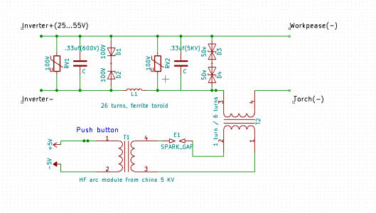
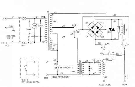
Even without being an electronics expert, consider the following typical circuit fragments. I will try a general explanation, but if electronics is not your thing, suffice to say that one circuit is all about stopping HF-start stuff from getting back and hurting the inverter electronics. Both circuits show the way HF start is added in series with whatever the welder produces, and only does it's thing briefly.
HF Arc Starter & Full Bridge IGBT Driver.png

TIG Circuit-2.jpg

In both cases, just notice the connections to the torch, and follow one lead back. See how it encounter's a thing with coils.
That RF coil, part of an RF transformer, is made from big fat conductors, and is the way to introduce the high frequency start in series with the the welder voltage. It is only effectively there briefly. When not introducing radio frequency voltages, the RF coil looks like a bit of fat cable coiled up, not affecting the regular weld currents in any way.

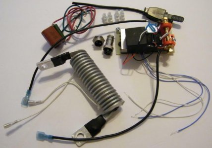
Here is a picture of the bits..
TIG HF Start Kit.jpg
Notice two white wires going into the coupling coil. They are for the RF resonant oscillator generating the radio-frequency voltage.
It might be air-cored, or it might have a ferrite rod up it - I can't tell.
- - - - - - - - - -
Many RF generators are the crudest possible, made exactly like the early Marconi spark transmitters for ships, using a spark gap with an induction coil. Many DIY designs just use a spark plug to provide the gap. Every splat sets the circuit ringing at radio frequency, which dies out, until the next spark. The spark seems continuous, while HF start is on, but it is really a series of separate sparks.

Notice the first circuit HF Arc Starter. All the bits to the top left are not the whole inverter, but a chunk of circuit devoted only to stopping RF and overly high voltages getting back into the inverter. D3 and D4 together will limit anything across them to 100V. Varister RV2 will short out anything over 100V.

The capacitors and inductor L1 form a low pass filter, blocking any RF. L1 needs to be made of thick stuff. The whole act is repeated upstream of L1, limiting voltage to 100V, with a belt-n-braces D1 with D2, at 200V, just in case the other fails.

The entire circuit fragment shows an extremely determined and elaborate provision to absolutely stop any high voltage shenanigans introduced by the HF coil transformer T2 from getting back into the inverter. It is a huge and deliberate protection circuit.
- - - - - - - - -

The second circuit is a "buzz box" welder circuit in it's entirety. No high tech IGBT switcher pulsed and arc current controlled waveforms here. It's just a transformer! OK then - it also has a bridge diode rectifier to deliver a DC option. The choke inductor "Z" blocks radio frequency energy getting back to hurt the bridge rectifier 4 diodes silicon rectifier "SR". Capacitors C1-C4 shunt any remaining RF. VR1 is a overvoltage protection device. C7, R2, and R3 are a snubber circuit, also to damp unwanted ringing. T3 is the gadget we are looking for. It's the series coupling RF transformer. Notice the spark gap G, and the step-up transformer T2. When the AC voltage is high enough to cause the spark to jump, the spark completes the circuit C6 and the inductance of T3, which rings at radio frequency.

So - anyone contemplating "adding" a HF start needs at least to understand exactly what they are doing, and how it works. That said, the bits are pretty cheap, perhaps amounting to 5% of a whole welder cost. I am unimpressed by all versions of "spark plug gap" oscillator I have seen so far. Those featuring a proper RF oscillator will interest me more.

In at least one YT video, the guy adds a sparkplug version to the welder, which initially messes it up, though it survives. He says it "seems to cancel" the welder. He "gets it to work" by introducing another spark gap in the lead in his handle add-on. Actually, it was "working" after a fashion, perhaps from a single little spark at the electrode. I DO NOT advise attempting anything like this. It's still too easy to damage a $800 welder this way.
 
Last edited:
Back
Top