Ischgl99: Cheap import bearings which could be why they're so far off. I like to keep an assortment of "cheap stuff" around for the odd non-vital jobs but it can definitely throw you off track sometimes.. I don't trust my 27.9 measurement entirely but it should be within +/- 0.03 when comparing to standards and my other measuring equipment.
David2011: That's what it intuitively felt like to me as well. I could apply much more torque than I was comfortable with before it slipped, at least on my two internal mics which are cheap imports. The The ratchet knob is much softer on the external digital mic and it feels much more "appropriate". I need to see if I can disassemble and service the cheap imports, maybe fix some of the calibration and stiffness issues..
Huub buis: That's a lot of great info, thanks!
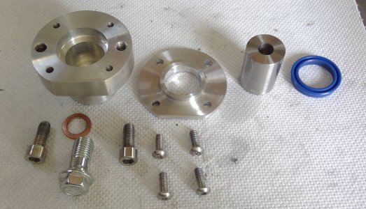
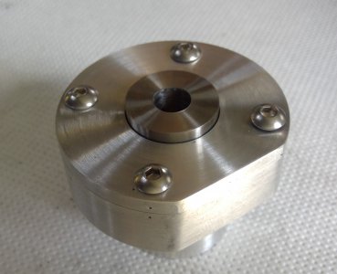
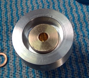
What I've done for these last practice pieces is start with a 50mm round stock, drill to 19mm and then start boring to 25.00mm in 0.5mm steps.
Since the machine is a "manual-converted-to-CNC" I've also been experimenting with automating it more.
The first two pieces I measured after every 0.5mm pass to dial in both feeds/speeds and actual diameter I was getting, being careful with temperature too.
The following parts I tried running an entire program, taking it from 19 to 24.5 and then measuring/adjusting program and only doing the final pass to 25.00 separately.
This amount of material removal of course tended to heat up the part quite a bit so I aimed for ~25.03(hot) which seemed to result in a tight sliding fit once cooled down, possibly not the best method but I'm impatient.

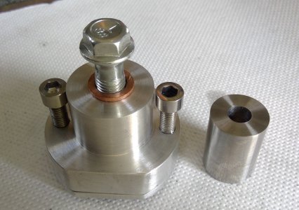
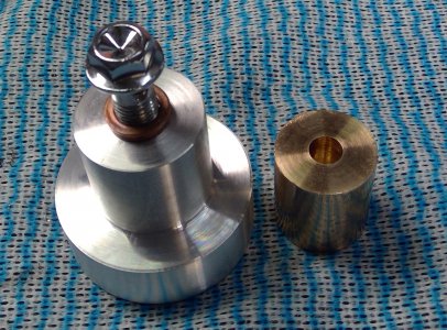
The pieces are 21mm thick and with the shaft of a 25mm end mill slid through, you can just barely feel the sideways movement.
To the best of my abilities the end mill seems to be around 24.9 to 24.94 ish so the hole itself should be very close to 25.00.
I think if I measure the sideways deflection a certain distance away from the hole and more accurately measure the end mill shank, I should be able to quite accurately calculate the bore size with trigonometry, could be an interesting experiment and give me something to "aim for" when testing the other measuring tools.