Adapting a large steady rest to my lathe.

ErichKeane

Making scrap at ludicrous speed.
H-M Lifetime Diamond Member
Joined
Aug 3, 2017
Messages
2,437
My 16" lathe didn't come with a steady rest, buying the one that comes with this lathe is basically impossible (I'd end up having to find a lathe that comes with one, buy it, and find a way to dispose of it), and the factory one was pretty mediocre. So, I figured I'd need to build one some day.

If been keeping an eye on eBay for one of the right size or so. One of the size of my lathe ends up likely not working, since the spindle isn't centered in the ways. I figured I'd have to buy a slightly larger one, then take some material off it( or make one from scratch!). Additionally, my lathe is 8 1/8 from the bottom to center, so I would need a larger side of 16" (or add material to the bottom). Most of that size ended up having about a 3" capacity though.

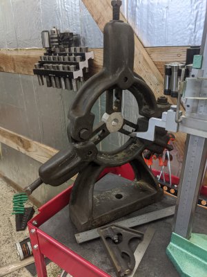
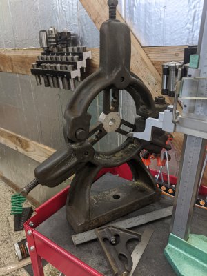
Imagine my surprise when I found one made for a 18" lathe that had a huge center circle, and looked in good shape! It was even pretty cheap! I did an offer on it for cheap and was instantly accepted.

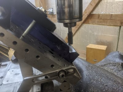
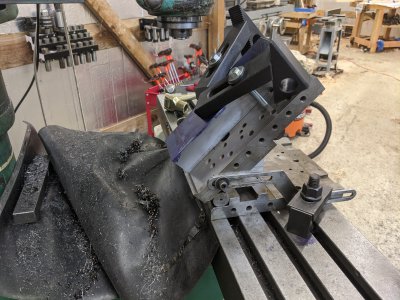
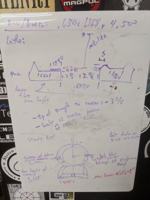
I finally got out to the shop today and ended up measuring out the new steady rest. IT has a 9 1/8 base to center, so I have to take an entire inch off the bottom, plus about 1/2" for the triangle cutout. Suffice to say, I need to cut the entire bottom off and bolt on a new one I think :/

I'm going to plan on finding a 2*3*12" piece of cold roll I think, machine the base of the current one off, then bolt up the new piece as new base. Not much material in the legs, but I have to work with what I've got I guess. Picture are of the steady rest and my white board measurements.
 

Attachments

  • IMG_20191229_164737.jpg
    IMG_20191229_164737.jpg
    2.2 MB · Views: 88
  • IMG_20191229_164738.jpg
    IMG_20191229_164738.jpg
    1.6 MB · Views: 81
  • IMG_20191229_164729.jpg
    IMG_20191229_164729.jpg
    1.2 MB · Views: 69
I recently fit a steady rest from a 10-inch lathe to my 9-inch lathe.

I did NOT get a steady-rest with my lathe either......and I have an upcoming project where I'll need one.
I found one on ebay and though the seller did NOT give lathe type/size, they did include decent photos with a ruler in them. Using those I determined that it would fit my v-ways perfectly, but was unsure about centre height....it was close, but hard to tell.

Anyway when I got it, it did fit the lathe ways perfectly, but the centre height is too high. I contemplated milling a 1/2-inch off the maybe 3/4-inch bottom of the rest and then cutting new vees. However, I did NOT want to compromise the integrity of it by hacking it up.

It came with brass tipped fingers and I knew I wanted roller-bearing fingers. So I made a set and I used two "tricks" to try and deal with the off-centred nature of the beast.

1) I made the fingers long enough that the top one could still centre lower in the circular cut-out of the steady rest, and

2) I made the bottom two fingers with the ends tapered and mounted the ball-bearings off centre towards the bottom.

These two strategies worked well. I did NOT modify the steady rest frame, and I made a few easy changes to the roller-bearing fingers I was making anyway. I have already used it a couple times, and it had performed very well.

Since the centre cutout in my steady rest is NOT on the lathe centre line it will restrict the maximum diameter of the work piece I can use with the steady rest.

I will try to post some pictures tomorrow!

-brino
Great! I'd love to see it! another problem i have is that it doesn't sit flat. So I'll have to do some milling anyways. Otherwise I'm about an inch high and ~1" back.
 
As promised, here are some photos of my steady rest.

The original as received:
original.jpg

I assume the "hook bolt" at the top was for hanging it up for storage.

Here's how it looked on the lathe with some random bar in the collet chuck:
orig_on_lathe.jpg

It fits the lathe ways perfectly, but the bottom two fingers are obviously NOT on the lathe centre-line.

Here's the base:
base.jpg

Now I could take a 1/2 inch off, but I like that big chunky base.

I thought about building some bent or "cranked" fingers to re-centre them.
I did up some sketches with new ball-bearing fingers and with the bearings offset it looked promising, so.......I built some:
new_fingers.jpg

new_fingers2.jpg

Here's how they look on the lathe:
new_fingers_on_lathe.jpg


new_fingers_on_lathe2.jpg

The fingers are all spaced 120 degrees from each other, but the contact points to the workpiece are NOT.....exactly.
Also, since my lathe centre and steady-rest centre are NOT the same this will limit the maximum work-piece diameter I can use with the steady rest.
However, it should meet my immediate needs.

I have used it a couple times and they worked great. I could easily dial out any run-out and they held the work firmly.

However your situation is different. You have an 18" steady rest on a 16" lathe, and so a much bigger offset to deal with.
Also, your base does not already fit your ways.

Please let us know how it goes!

-brino

original.jpgorig_on_lathe.jpgbase.jpgnew_fingers.jpgnew_fingers2.jpgnew_fingers_on_lathe2.jpgnew_fingers_on_lathe.jpg
 
Last edited:
That is a really interesting solution! Thank you for sharing! You also would have had a big problem with the 'V' getting into the 'leg'. Mine ends up being to the middle of the 'leg', so I think it would poke through if I were to recut it. My one concern with your setup would be that you're not really supporting the bottom of the material as well as a steady rest does. Possibly it doesn't matter, but I'd guess you have to be a little more ginger about tightening the top one down.

At the moment, my plan of attack is going to be to make the new 'base' before touching the steady rest. I think I'm going to go buy some material today and at least cut out a piece to match my ways. If I can get it accurate enough that I think it'll work (and get the steady rest bottom into the mill enough to mill the legs flat), I'll then go forward.

My biggest concern at the moment is how I can attach the new base to the 'legs' of the steady rest. The leg material is pretty thin (I want to say ~1/4" in a T). I won't be able to weld it (I don't have one, and its cast iron to 1018 even if I could!), and I don't think a braze would work (again, even if I could!). My only real solution would be to use some cap head bolts through the bottom, likely something in the M3/M4 range or #6/#8 range. Perhaps a little bigger if I can get away with it.
 
Personally, my first choice would be brazing. I think that would be super strong. However, if you don't have the tools or cannot find someone to do it for a reasonable price then bolting should also work.
-brino
 
Personally, my first choice would be brazing. I think that would be super strong. However, if you don't have the tools or cannot find someone to do it for a reasonable price then bolting should also work.
-brino

At the moment I don't have the equipment... I guess a cheap brazing torch is only $70 so I should be able to figure it out. But heating cast iron gives me the willies :) I guess I have a decent amount of time to think about it though.
 
At the moment I don't have the equipment... I guess a cheap brazing torch is only $70 so I should be able to figure it out. But heating cast iron gives me the willies :) I guess I have a decent amount of time to think about it though.
Heating cast iron shouldn't give one the willies. It's stable and won't be a problem as long as it's not cooled suddenly. However, learning brazing by beginning on your steady rest is not recommended. Practice on several scrap cast iron parts.

jack vines
 
Alright, got some work done today! I ended up buying a 1.75"x3"x12" piece of 1018 that had to be shipped (no one here locally had more than a 1" piece, and since I've got to go at least 1/2" of material to remove for the 'triangle'. First, I cut it on the bandsaw down to a little more than 9", I need 9.1" long or so in order to let it get between my carriage. Then, squared it up:

IMG_20200103_142650.jpg

I straightened the ends, then used my center finder to find the center of the piece with my DRO:
IMG_20200103_151921.jpg


Then, I center drilled it. I'm going to need this hole for the bolt anyway, so I figured I'd put a center in it so I can find the hole easy enough next time:
IMG_20200103_152845.jpg

Then, I used my DRO to find the offsets of the center of the triangle-ways and flat way, then used a chamfer tool to make the marks:
IMG_20200103_154050.jpg

Then, took it to the bench to mark the ways:
IMG_20200103_155040.jpg

Next step is to remove my vice and set this up on the sine plate so I can cut the triangle. I presume I will cut it a little deep, then via trial/error cut the 'flat' side until it sits perfectly level. I left it a bit thicker than I want it in the end (a little less than 1.5", figuring I need it at 1.375" at minimum) so that I can mill a bit more off if I cut the triangle too deep! I also want to surface grind the ways side, so a bit extra for that is a good idea too I think.

Thats it for now :)
 
Did a little more work today. Got the triangle cut as well as the flat. Everything worked out great so far except for one endmill that died while I was cutting the 45 and moved it in my setup. Fortunately it was small enough of a mess up and early enough that I was able to reset and cut again.

I ended up overcutting the triangle slightly, so I needed to mill down the thin part in the side, but after that it fit perfectly!

Next step is to round corners and get it thinned out a little to lighten it a touch. After that, I need to make the other side of the clamp, followed by modifying the steady rest to fit!
 

Attachments

  • IMG_20200104_130012.jpg
    IMG_20200104_130012.jpg
    3.8 MB · Views: 35
  • IMG_20200104_133849.jpg
    IMG_20200104_133849.jpg
    3.8 MB · Views: 33
  • IMG_20200104_130012.jpg
    IMG_20200104_130012.jpg
    3.8 MB · Views: 32
  • IMG_20200104_133849.jpg
    IMG_20200104_133849.jpg
    3.8 MB · Views: 38
Back
Top