Started adding a tach magnetics for a readout in TouchDro. I have the Glass/Magnetic Scale Adapter https://www.touchdro.com/resources/getting-started/glass-scale-adapter.html.
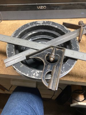
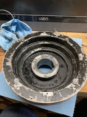
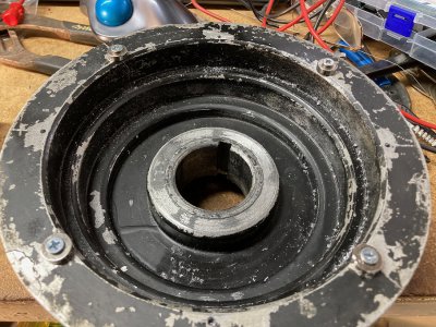
I started by drilling and taping 8 holes in the bottom of my spindle pulley. I plan to start with 4 magnetics but went ahead and added an additional 4 holes so they could be added if needed.


Yury started the post about the new adapters at just the right time as I was just starting to think about what connector to add for the magnetic pickup. With the new adapter having s video connector I decided to use that one. I do plan to add a DRO to my lathe later and when I do I will use the adapter I have for that and purchase a new one for the mill. Having the same connector will make it just a plug and play when I do change.
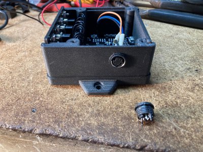
Forgot to get pictures and will try to add them later but here is the connector I used. https://www.amazon.com/dp/B00CQNU5TK?psc=1&ref=ppx_yo2ov_dt_b_product_details. I was able to take a 1/2-20 die and thread the outside of the connector and then drilled and taped the side of the housing and screwed the connector into it.
Here is the pickup that I used. https://www.amazon.com/dp/B0859SB83M?psc=1&ref=ppx_yo2ov_dt_b_product_details I held it below the magnetics with the mill running and I did not get any readout on the display. I held it fairly close but not as close as it would be when it gets mounted.
So here is my question for Yury or anyone else who is knowledgeable in this. Should this pickup work or do I need a different one? If this one should work I will go ahead and mount it so I can get it closer to the magnets. If not I will get the needed pickup and mount that one.
I started by drilling and taping 8 holes in the bottom of my spindle pulley. I plan to start with 4 magnetics but went ahead and added an additional 4 holes so they could be added if needed.


Yury started the post about the new adapters at just the right time as I was just starting to think about what connector to add for the magnetic pickup. With the new adapter having s video connector I decided to use that one. I do plan to add a DRO to my lathe later and when I do I will use the adapter I have for that and purchase a new one for the mill. Having the same connector will make it just a plug and play when I do change.
Forgot to get pictures and will try to add them later but here is the connector I used. https://www.amazon.com/dp/B00CQNU5TK?psc=1&ref=ppx_yo2ov_dt_b_product_details. I was able to take a 1/2-20 die and thread the outside of the connector and then drilled and taped the side of the housing and screwed the connector into it.
Here is the pickup that I used. https://www.amazon.com/dp/B0859SB83M?psc=1&ref=ppx_yo2ov_dt_b_product_details I held it below the magnetics with the mill running and I did not get any readout on the display. I held it fairly close but not as close as it would be when it gets mounted.
So here is my question for Yury or anyone else who is knowledgeable in this. Should this pickup work or do I need a different one? If this one should work I will go ahead and mount it so I can get it closer to the magnets. If not I will get the needed pickup and mount that one.


