Allen Bradley VFD

John_Dennis

Active User
Registered
Joined
Mar 5, 2014
Messages
381
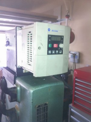
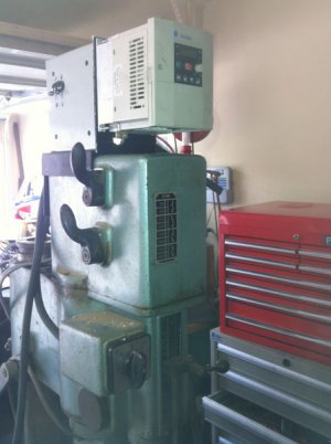
I have acquired a pair of Allen Bradley Bulletin 161 VFDs.

I see that they are capable of having a digital or analog remote.

How can I build a remote for Forward-Stop-Reverse

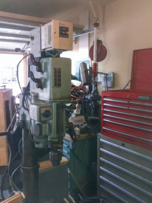
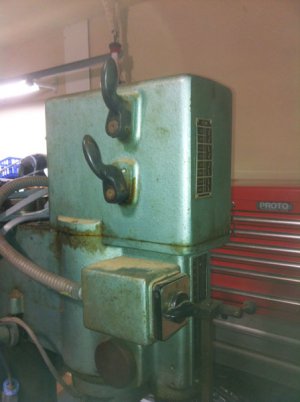
I have this VFD installed on a Arboga Gear Head Drill Press made in Europe. In its original 3phase 440 configuration you could turn the rotary switch from forward to reverse for tapping operations. Currently the VFD gives an error when the rotary switch is moved while running.

This unit makes a horrible high pitched whine, is this normal?

Thanks

John

PS My account was deleted for some reason, I do not have access to my previous post about this drill press.
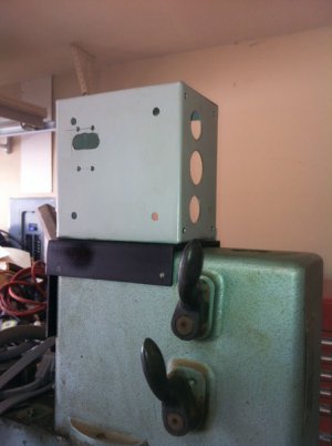
IMG_1374.jpg IMG_1375.jpg IMG_1377.jpg IMG_1378.jpg IMG_1380.jpg
 
Last edited:
How do you have the VFD wired in? The proper wiring would be Switch -> VFD -> Motor. Use the switch as the main power for the VFD. Never put a switch between a VFD and the motor.

http://literature.rockwellautomation.com/idc/groups/literature/documents/um/161-um000_-en-p.pdf

Here is a link to product manual. See page 7 for motor wiring, See page 9 for Control wiring. Digital inputs 1-5 are programmable so you can assign them to functions like FOR/REV

If you have more questions, I'll be happy to go in to more depth.
 
The original configuration is a 5 position switch. 1,2,0,1,2 which provided 2 reverse, off, and 2 forward speeds. The motor runs best in position 2 high, but has trouble starting in 1.

The rotary switch has a lot of wires, I am afraid to mess with it.

If I am understanding the diagram correctly, I can put a momentary switch on 1-3 and program forward, stop, reverse.

I do not understand the diagram for the potentiometer, I have nearly no experience with low voltage circuitry.

Thanks,

John
 
As far as the Main switch goes, there should be only 3 wires going to the motor unless it is a 2 speed motor. then there would be 6 wires.

You can rewire the switch to only interrupt power to the VFD. 3 wires in, 3 wires out. An alternative would be to completely bypass the main switch on the machine and use a 3 pole disconnect to provide a main power switch.

Edit: I took a look at the pictures of your machine again, I would just put the main switch in the high speed position and leave it there. Use an external disconnect to switch main power.


In this case
Terminal 1 would connect to H
Terminal 2 would connect to O
Terminal 3 would connect to L and GND

I could have terminals 1 and 3 reversed in the explanation.

Radio Shack will have a pot that will work. Be sure to buy a Linear Taper pot, not an Audio Taper.


I would only use a 3 wire circuit for the FOR/REV with a center OFF position, and use terminals 1 and 2, with power supplied by P24 on the VFD.

To fix the slow start, you may need to adjust the Slip Compensation as needed.
 
Last edited:
As far as the Main switch goes, there should be only 3 wires going to the motor unless it is a 2 speed motor. then there would be 6 wires.

You can rewire the switch to only interrupt power to the VFD. 3 wires in, 3 wires out. An alternative would be to completely bypass the main switch on the machine and use a 3 pole disconnect to provide a main power switch.

Edit: I took a look at the pictures of your machine again, I would just put the main switch in the high speed position and leave it there. Use an external disconnect to switch main power.


In this case
Terminal 1 would connect to H
Terminal 2 would connect to O
Terminal 3 would connect to L and GND

I could have terminals 1 and 3 reversed in the explanation.

Radio Shack will have a pot that will work. Be sure to buy a Linear Taper pot, not an Audio Taper.


I would only use a 3 wire circuit for the FOR/REV with a center OFF position, and use terminals 1 and 2, with power supplied by P24 on the VFD.

To fix the slow start, you may need to adjust the Slip Compensation as needed.


Thanks Jim, that is very helpful. Are the digital inputs designed for a momentary switch or a regular switch.

John
 
Last edited by a moderator:
Thanks Jim, that is very helpful. Are the digital inputs designed for a momentary switch or a regular switch.

John


Normally in this configuration you would program the inputs for a maintained contact (regular) switch. See page 9 of the manual
 
Last edited:
Back
Top