Apron can be picked up off the ways by about 1/8 inch; is this OK?

I'm already upside down according to your world view!:rolleyes:
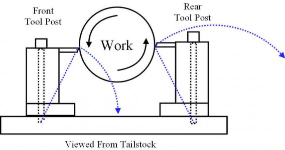
No, I keep my eyes open when parting and I usually sit down or stand on both feet facing the lathe. The reason I use an 'upside down' parting tool and run the chuck clockwise is that the chips or swarf falls down and it just works better. I part at nearly the same speed I turn at, fast and hassle free.
I was incorrect when I said I use a LH tool for boring though, I use a RH tool upside down from conventional cutting on the rear side of the lathe as it allows me to see what I am doing easier if I am doing something narly. If you ever have to bore out a track roller some genius has decided to blast weld into after a non-maintained bearing has collapsed and done so without removing all the broken bearing I can assure you that being able to observe the cut is pretty much vital.
I have never had any problem boring to size.
Some of us have screw-on chucks, that gets hairy.....
 
P.S. For upside down parting off the forces are downwards into the apron. I have a reasonably sturdy lathe but on lighter lathes lack of rigidity is what cause parting problems due mainly to the lifting forces on the toolpost which is why long before I was born people started mounting parting blades on rear toolposts.
# Having worked with ancient lightweight clapped out badly worn small lathes I can tell you that parting upside down makes a huge difference.
 
P.S. For upside down parting off the forces are downwards into the apron.

Are you sure about that? If the tool is upside down in the rear, the spindle is rotating CCW into the tool. It is used this way because any catch will move the tool away from the cut (as opposed to parting normally, when a catch will try to pull the tool into the work, thus a broken blade). It is the vertical play in the carriage that allows the tool to lift out of the way when used upside-down - not possible if the forces are downwards into the apron.
 
Well, the lathe is designed for the forces to go into the bed - not into the air. I suppose that you could mount the lathe upside-down on the ceiling and use it like that, but that's not how it was designed. We often hear, "I part backwards, standing on one leg with my eyes closed and it works for me..." All that tells me is that their lathe isn't set up properly for parting, or their technique is bad. And why would someone routinely bore with a LH tool? Every "lift" of the carriage will change the bored radius (not much, but it does change). If you're using carbide, boring with a LH tool seems like a recipe for fracturing the insert.
Intuitively I would have guessed exactly what you are saying. Otherwise the manufacturer would have gone to the same lengths with the underside of the ways as they did on the top side.
 
Are you sure about that? If the tool is upside down in the rear, the spindle is rotating CCW into the tool. It is used this way because any catch will move the tool away from the cut (as opposed to parting normally, when a catch will try to pull the tool into the work, thus a broken blade). It is the vertical play in the carriage that allows the tool to lift out of the way when used upside-down - not possible if the forces are downwards into the apron.
Yeah, pretty sure.
I even went out this morning and knocked up a mock-up out of a couple of pieces of wood and a bit of bar to check I am not as deluded as most suspect me to be! What was that saying about levers?
In turning from the front there is a lifting force at the base of the toolpost. This is countered by the lever arm of the cross slide, the mass of the cross slide and tool post and the gibs on the dovetail which transfer forces to the apron and on into the mass of the lathe.
I am sure someone smarter than me will now demolish me mathematically. :frown:
On another note I think that with parting lack of rigidity, tool geometry and that heinous backlash contribute most to problems.

As to twooldvolvos original question I think that has been answered. Adjust cross slide gibs and apron anti-lift pads/retainers?
 

Attachments

  • rear Toolpost.jpg
    rear Toolpost.jpg
    44.1 KB · Views: 14
Yeah, pretty sure.
I even went out this morning and knocked up a mock-up out of a couple of pieces of wood and a bit of bar to check I am not as deluded as most suspect me to be! What was that saying about levers?
In turning from the front there is a lifting force at the base of the toolpost. This is countered by the lever arm of the cross slide, the mass of the cross slide and tool post and the gibs on the dovetail which transfer forces to the apron and on into the mass of the lathe.

Well, you have the drawing correct, but you interpreted it wrong. The force is coming from the WORK, so in the front toolpost, the force is going INTO the bed. Inversely, the force from the work in the REAR toolpost is going into the AIR.
 
Well, you have the drawing correct, but you interpreted it wrong. The force is coming from the WORK, so in the front toolpost, the force is going INTO the bed. Inversely, the force from the work in the REAR toolpost is going into the AIR.

I think the simplest thing is for you to take two pieces of scrap wood very roughly in the same relationship size wise to your lathe cross slide and toolpost and nail/screw the smaller to the larger. attach something be it another piece of wood , a bit of steel rod as I did to the 'toolpost' piece, pivot the whole about the base directly under the 'toolpost' and apply a force downwards on whatever is representing your cutting tool.
Visibly observe which way the base tilts.
Go back and look at the drawing again.
I know it seems counterintuitive but hey! Perhaps physics work differently up here? I mean just look at how water goes down the plughole backwards where you are.
 
Here's a simplified free-body diagram of the front toolpost (there are rotational moments that just complicate things). The rotating work imparts a downward force F1 into the toolpost (I don't show the work force). The toolpost resists this force by exerting an upward force also of F1. To prevent the toolpost from flying off into space, a corresponding downward force F2 (equal to the work F1) into the bed. A free-body diagram is complete when ALL vertical and ALL horizontal forces sum to zero.

The same diagram can be used for the rear toolpost, except the forces are opposite.


TOOLPOST.jpg
 
Are you sure about that? If the tool is upside down in the rear, the spindle is rotating CCW into the tool. It is used this way because any catch will move the tool away from the cut (as opposed to parting normally, when a catch will try to pull the tool into the work, thus a broken blade). It is the vertical play in the carriage that allows the tool to lift out of the way when used upside-down - not possible if the forces are downwards into the apron.

Let us start by ignoring bending moments on the tool post.
Let us, instead, concern outselves with how the force on the part is being absorbed by the machine.

Tool at front, CCW, the work on the part is pushing the cariage onto the ways at the front of the lathe
Tool at rear, CCW, the work on the part is lifting the cariage away from the ways at the back of the lathe

The bending moments in the tool, its holder, the QCTP, the compound, and the cross slide are small compared to the forces mentioned above.

Tool at front upside down, CW, the work on the part is lifting the cariage from the front ways--this arangement is used in common threading application where DoC is light.
 
Tool at front, CCW, the work on the part is pushing the cariage onto the ways at the front of the lathe
Tool at rear, CCW, the work on the part is lifting the cariage away from the ways at the back of the lathe

Isn't this what I said? If not, that is what I intended to say.

Tool at front upside down, CW, the work on the part is lifting the cariage from the front ways--this arangement is used in common threading application where DoC is light.

When is this setup ever used? I've never threaded, common or otherwise, like that. All that mounting the tool so that the forces are UP does is decrease rigidity.

SETUPS IN ORDER OF RIGIDITY:
1) TP front, tool up, CCW
2) TP back, tool up, CW (#1 and #2 are equal)
3) TP front, tool down, CW.
4) TP back, tool down, CCW.

#3 is more rigid than #4 because of the lever arm of the carriage, since the front of the carriage has little vertical play.
 
Back
Top