Arduino based rotary controller project

revwarguy

Active User
Registered
Joined
Mar 24, 2012
Messages
33
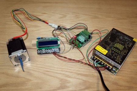
I've built a stepper motor driven indexing controller made from off the shelf parts of an arduino, stepper controller, and a display shield for the arduino.

It's use, build log and video of operation is described here, and it will be included as an article in Digital Machinist shortly. The code for the arduino will be available from the magazine's website.

wiring.jpg

wiring.jpg
 
I've built a stepper motor driven indexing controller made from off the shelf parts of an arduino, stepper controller, and a display shield for the arduino.

It's use, build log and video of operation is described here, and it will be included as an article in Digital Machinist shortly. The code for the arduino will be available from the magazine's website.

View attachment 67754
Yesterday, I got serious about restoring the Denford micromill I bought at an auction three years ago. After a few hours of studying schematics and researching on-line, I got the X and Y axes to move manually and could control the number of steps and the direction. Man, was I excited. The Z axis connnector had been ripped out of the stepper, so some careful resoldering was required. Either my rewiring wasn't careful enough or a pre-existing Z axis problem was the reason the machine was auctioned. In any case, when I plugged it back in, one of the output drivers burst into flames. And now I'm back at square one (or maybe some large negative number).

I've spent the last 24 hours debating whether to tear the whole thing apart and basically rebuild it OR to build my own design using the two good steppers, spindle and table along with an Arduino/Raspberry Pi based H bridge controlled power supply. Your brilliant post is perfectly timed for me. I'd sure read any of your updates religiously. Thanks for your hard work.
 
I've spent the last 24 hours debating whether to tear the whole thing apart and basically rebuild it OR to build my own design using the two good steppers, spindle and table along with an Arduino/Raspberry Pi based H bridge controlled power supply. Your brilliant post is perfectly timed for me. I'd sure read any of your updates religiously. Thanks for your hard work.

Thanks, Arlo. From your post, though, I am not sure what you are planning - do you want a full 3 axis CNC machine? If so, then the stepper driver I used in my first post might not be good enough for that. I chose it because it was cheap, and for my application there is no need for speed or much torque to speak of. If I were going to CNC a mill, where speed and torque do matter, I would use a better stepper driver, like a Gecko g540 or bigger, depending on the kind of mill you have. Also, you would probably need a full PC to run Windows/Mach3 to drive the thing as G-code interpretation and bit diddling a parallel interface is very compute intensive, beyond the capability of my Arduino, so far. (I am showing my experience, er, bias, here in that the computer could also be running Linux and LinuxCNC - but AFAIK a Raspberry Pi also doesn't have the horsepower for that, either, but I could be wrong about that since I don't follow that world much.)

Anyway, there are lots of guys that converted their mills to CNC - there are forum groups on CNCZone.com or Yahoo groups or Google groups that discuss just that.

I don't want to discourage innovation here - if you really do want to try to use the setup to do something in between manual and a full CNC - kind of like a smarter power feed/DRO on each axis, then this might be a good place to start, but I would look at enhanced speed control, and some feedback for end stops and/or home positions. (I built my own power feed on my mill, shown here, but I used a cheap gear motor, not a stepper. I guess you could swap that with this setup.)

If you did this, your out-of-pocket would be about the same as for a full Linux CNC, though, but now you need to deal with the world of CAD.
 
Last edited:
My Denford is based on Sherline similar to this http://www.use-enco.com/CGI/INPDFF?PMPAGE=524&PMITEM=505-6694 but with Denford electronics and motors. The steppers are 2 amp Nema 23. I think the steppers in my machine are operational but I did order a NEMA23 Stepper with 185 oz in holding torque. I think the motor you used had a holding torque of about 80 oz in. I got this to replace the motor with the damaged connector on the Z axis in case it has bigger problems. I think I'll counterbalance this axis to further reduce the load on the stepper.

My initial goal is 3 axis DRO with manual jog in all three directions and spindle speed control/read-out. You raise good issues about the Arduino's limited capabiities if I want a true CNC. I think there are alternatives that I'll consider once I get a better handle on my processing requirements. The Arduino Mega would provide some more processing than the Uno and I think both the Beagle Board Black and the Raspberry Pi could be suffiecient. Another approach is to write the Gcode on a desktop and then transfer the raw coordinate data to the mill via an SD card read by the arduino. And of course, there's always Blue Tooth and 801 wireless.
 
"My Denford is based on Sherline similar to this http://www.use-enco.com/CGI/INPDFF?PMPAGE=524&PMITEM=505-6694 but with Denford electronics and motors. The steppers are 2 amp Nema 23. I think the steppers in my machine are operational but I did order a NEMA23 Stepper with 185 oz in holding torque. I think the motor you used had a holding torque of about 80 oz in. I got this to replace the motor with the damaged connector on the Z axis in case it has bigger problems. I think I'll counterbalance this axis to further reduce the load on the stepper."

The stepper I used is # 57BYGH310 at Circuit Specialists and has a holding torque of 24 kg-cm which is 333 oz-in.

"My initial goal is 3 axis DRO with manual jog in all three directions and spindle speed control/read-out. You raise good issues about the Arduino's limited capabiities if I want a true CNC. I think there are alternatives that I'll consider once I get a better handle on my processing requirements. The Arduino Mega would provide some more processing than the Uno and I think both the Beagle Board Black and the Raspberry Pi could be suffiecient. Another approach is to write the Gcode on a desktop and then transfer the raw coordinate data to the mill via an SD card read by the arduino. And of course, there's always Blue Tooth and 801 wireless
."

The Mega should be able to do it - come to think of it, most reprap 3d printers use a Mega Arduino with a stepper driver shield, like a RAMPS or RUMBA, and they do g-code interpretation as well as pulse drive their steppers.

I've also seen some interfacing to be able to read the inexpensive units like I used for the DRO's on my mill, shown in the link below. If the Arduino could read those, it could get and display position, as well as have positive feedback on movement. I would lean toward a larger more graphic display than the 2x16, though. There may not be enough control pins for everything, though, especially if you want to have a pendant-type control box.

PS Love Dayton, been to Wright-Pat many times
 
Last edited:
The stepper I used is # 57BYGH310 at Circuit Specialists and has a holding torque of 24 kg-cm which is 333 oz-in.

I missed this motor when I visited Circuit Specialists. It sound much better than the one I ordered so I've ordered it, too.

PS Love Dayton, been to Wright-Pat many times

Coincidentally, I bought my Denford via on-line auction from the Springfield, Missouri school district.
 
I'm still waiting for my components to be delivered but I have come up with a few questions:
1. Is protecting the motor controller from voltage spikes done on the controller circuit board? The schematic I found at Sainsmart isn't very clear but does not show discrete diodes/capacitors on the motor outputs. I've looked at the Toshiba literature but it isn't clear how the 6560 protects itself. It shows pin 19 as "Protect" but the notes say this is an output. Should I be concerned with providing protection against voltage spikes?

2. In my recent stepper motor education I've found a couple of sites that recommend controller voltages that are 5 to 10 times higher thant the stepper motor rated voltage. The stepper you're using (and one that I've ordered) are rated at 8.6 volts. Is there a reason that your power supply is 12 volts?

3. In your video, there is a semi-conductor hanging between the Arduino and the controller board. Is this the second thermal sensor.


Thanks again for your write-up. So far I've figured out how to energize my spindle and I've rigged up a test using DPST switches to test my original Z-axis stepper. Using this test set up, I've learned that the stepper works correctly and that my probme must have been in the Denford motor driver.

arlo
 
I'm still waiting for my components to be delivered but I have come up with a few questions:
1. Is protecting the motor controller from voltage spikes done on the controller circuit board? The schematic I found at Sainsmart isn't very clear but does not show discrete diodes/capacitors on the motor outputs. I've looked at the Toshiba literature but it isn't clear how the 6560 protects itself. It shows pin 19 as "Protect" but the notes say this is an output. Should I be concerned with providing protection against voltage spikes?

The TB6560 driver is not a great driver - I chose it primarily because it is inexpensive and this application is probably the least demanding of stepper performance that I can think of, making them a good fit. I can report that I've played with this thing quite a bit and haven't had any failures with it. However, DON'T disconnect the stepper from the driver with the power on - this is true for ANY driver, with protection or not! I haven't actually tried that, but then again, I know better! If you want to upgrade to a better driver, I can heartily endorse the Gecko drives that are out there, as I use them for my CNC work but they are 3-4x in cost.

2. In my recent stepper motor education I've found a couple of sites that recommend controller voltages that are 5 to 10 times higher than the stepper motor rated voltage. The stepper you're using (and one that I've ordered) are rated at 8.6 volts. Is there a reason that your power supply is 12 volts?

Going to a higher voltage will make the stepper more efficient as well as increase its top speed. Do we really need that in this application? Speed wasn't much of an issue here for me. I chose 12v because the Arduino only goes up to 12, and I wanted to keep it simple with a single supply. There is a 24v version of the Arduino, called a Taurino, which would let you double the voltage if you feel you need to without changing anything else. Or, you could use an even higher voltage (up to the rated limit of the driver) if you broke off the Arduino's 12v with a 7812 regulator or any other dual voltage power supply kind of arrangement.

3. In your video, there is a semi-conductor hanging between the Arduino and the controller board. Is this the second thermal sensor.

Yep, I just hadn't had a chance to use the thermal epoxy to adhere the temp sensor to the heatsink before I shot that video. I have seen little to worry about in terms of overheating, so you can skip the temp stuff if you want, but the sensors are very cheap and I like to be able to measure things. Perhaps in the next version of the software I'll make the temp mode easily removed from the firmware at compile time.

Good questions! Let me know when you get your parts!
 
Last edited:
Thanks for your response.

I regularly see threads about sharpening drill bits. There's an interesting one going right now. Have you considered the possibility of adapting your digindexer to this? I sometimes try to sharpen bits by hand but I agree 100% with the davidh's comment that "I don't have enough Saturdays left in my life".

Could the indexer be set at the proper angle on the mill table and then rotated to the proper orientation. With a grinding stone in the mill, advance the table to grind. Retract, rotate exactly 180 degrees (using the digindexer's accuracy) and repeat? Maybe a similar process would work for mills with the rotation a function of the number of flutes.

Or is the initial angular/rotational alignment too difficult to get accurate enough?
 
Back
Top