- Joined
- Nov 25, 2015
- Messages
- 335
Good morning all.
Last night I managed to complete what has been a long and arduous project that taught me a number of lessons; some of which I am happy to pass along this fine Saturday morning.
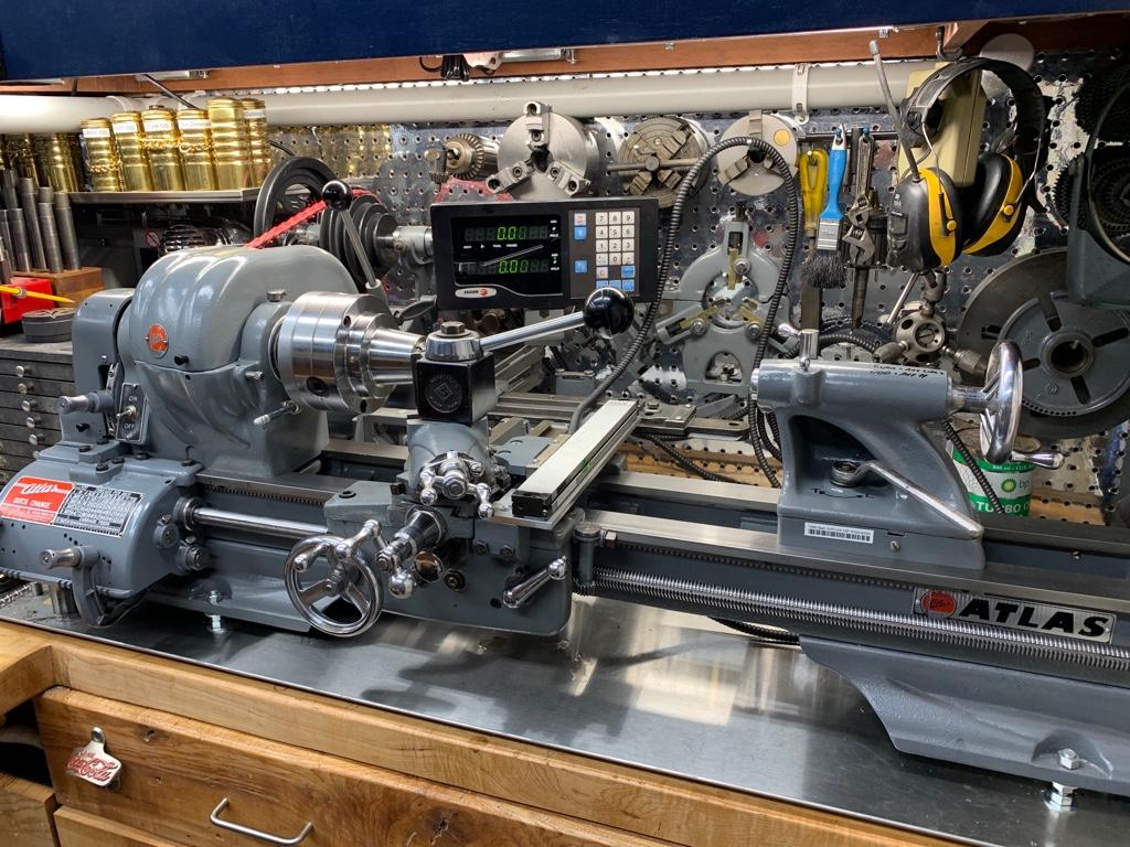
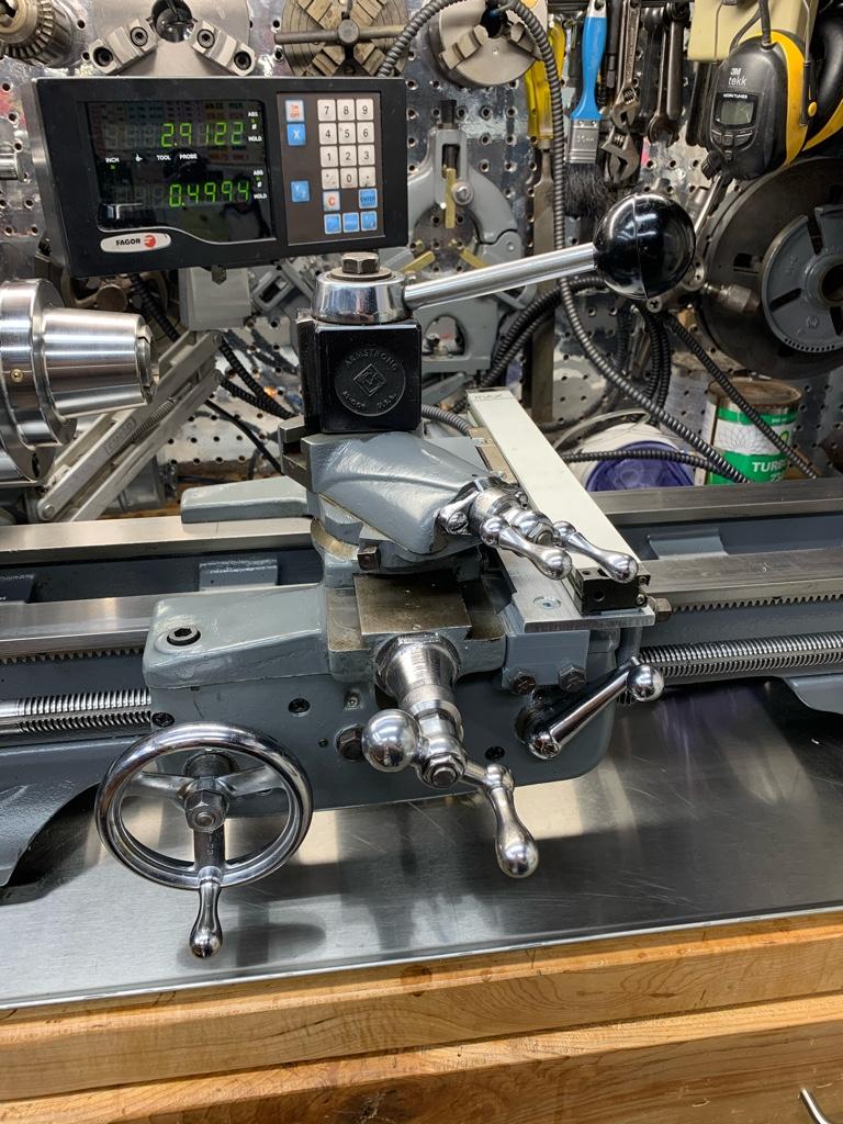
The DRO is a Fagor NVK-20. I purchased it about 4 years ago for $70 (CAD) at an auction. I had been looking through the auction listing online and saw the Unit. It was in an equipment auction and was notably “out of place” amongst the graders, loaders, backhoes, dump trucks etc. so I bid and ended up with it. Not until I went to pick it up did I find out that the glass scales came with it. “SCORE!”
One scale was 50”, the other was 19”. I watched any and all Youtube videos relating to cutting glass scales and decided my skillset and risk tolerance were not sufficient enough to attempt to cut them. Too, knowing how much a Fagor DRO costs new (I just bought an ACU-RITE 3 axis for my mill) the though of how bad I would feel if I screwed up precluded me from proceeding.
Along came Covit-19 and I was organizing, cleaning and re-jigging the shop. I came across the DRO unit and put it onto my bench...... I decided that it was time “**** or get off the pot”. The project took a full week of shop time but turned out reasonably, for a rookie.
My first issue was cutting the glass scales. This was not as challenging as first thought. In fact the first one only took about 10 min to cut. I used a Foredom (a big Dremel) cutter with a metal cutting disk to cut the aluminum around the glass, then a glass cutting “diamond” wheel to cut the glass. What I learned was that I needed to leave more supporting material (aluminum channel) before cutting the glass itself. When the fine folks at Fagor manufactured the glass scales, the piece of glass is supported along its entire length so it cut well and there didn’t seem to be any vibration issues causing cracks or breaks along the scale. After the cut I noted a small chip at the cut end which didn’t affect things in the least. I cleaned the scale with a blast of compressed air then got up inside with a blue paper shop towel moistened with 99% isopropyl alcohol and ran it full length. Both scales were cut the same way. It wasn’t until after cleaning the second one that it occurred to me that the blue shop towel might scratch the glass in some way, but it turns out that those scales are pretty resilient and even if I did scratch them to some degree, they are dead accurate.
The second scale when cut did crack about 2 inches in from the end. I’m not certain why because I took more precautions with it being closer to completion when it was cut. Fortunately because I was cutting the 19” in half (to fit the cross slide) I just used the other piece. I should add here that I cut, fitted and installed the X axis first before cutting for the Y (cross slide).
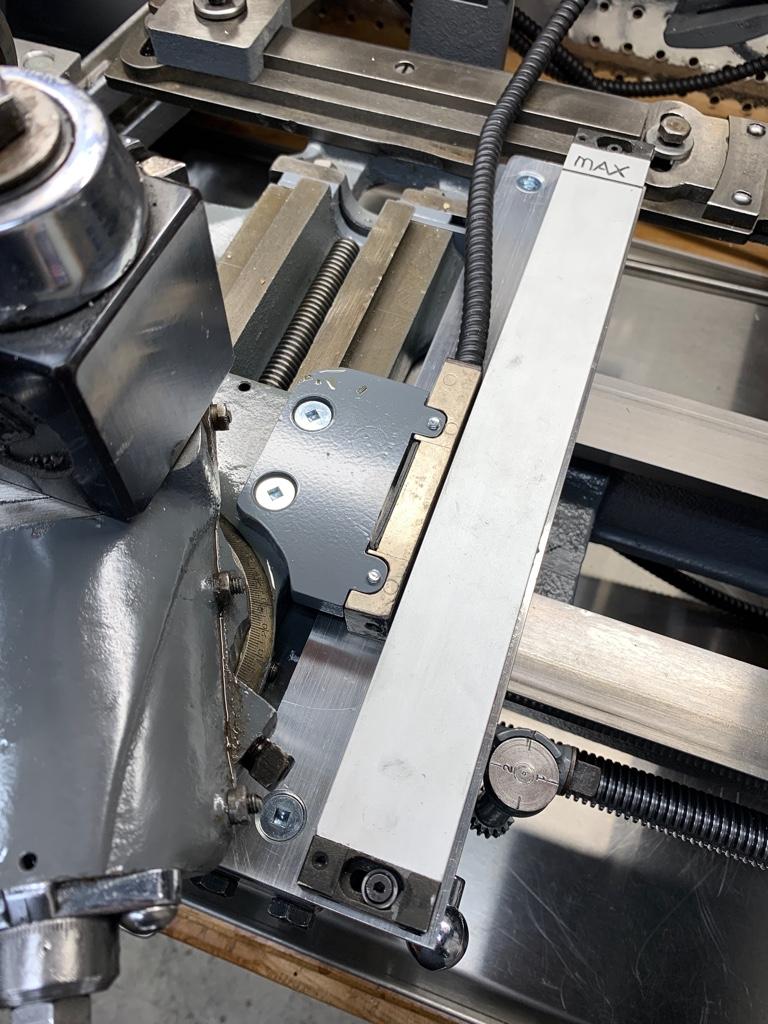
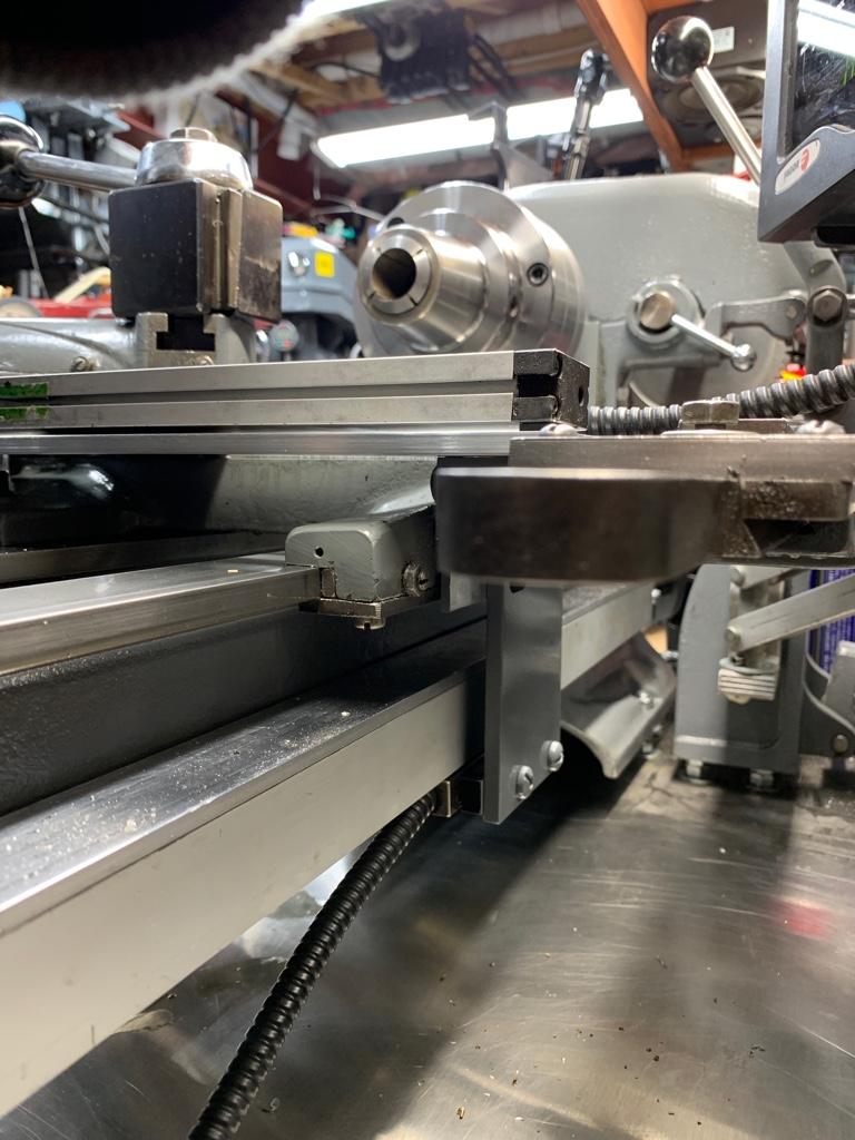
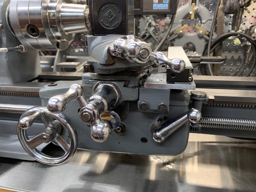
The cross slide required a great deal of thought. As anyone who owns one if these little Atlas/South Bend/Logan/Myford lathes, rigidity is often an issue. I needed a spot to mount the glass scale that was flat; which is nowhere on the Atlas carriage. I wanted to mill a flat on/into the saddle but was concerned that removing stock would affect rigidity. I “himmed and hawed” over placement, headstock side, tailstock side and settled on the tailstock side option. I wanted the scale to be protected from the headstock and the debris that comes from my repeated attempts to turn stock into chips. Further, the number of times I use my tailstock (and yes, this might be ignorance talking) is far less than what I’d have thought. And in most cases the reach will not be an issue. So tailstock side it was. I have really only lost about 2.7 inches, but if it was really necessary to do so, I can remove the apparatus; the slide can be removed temporarily in about 5 min.
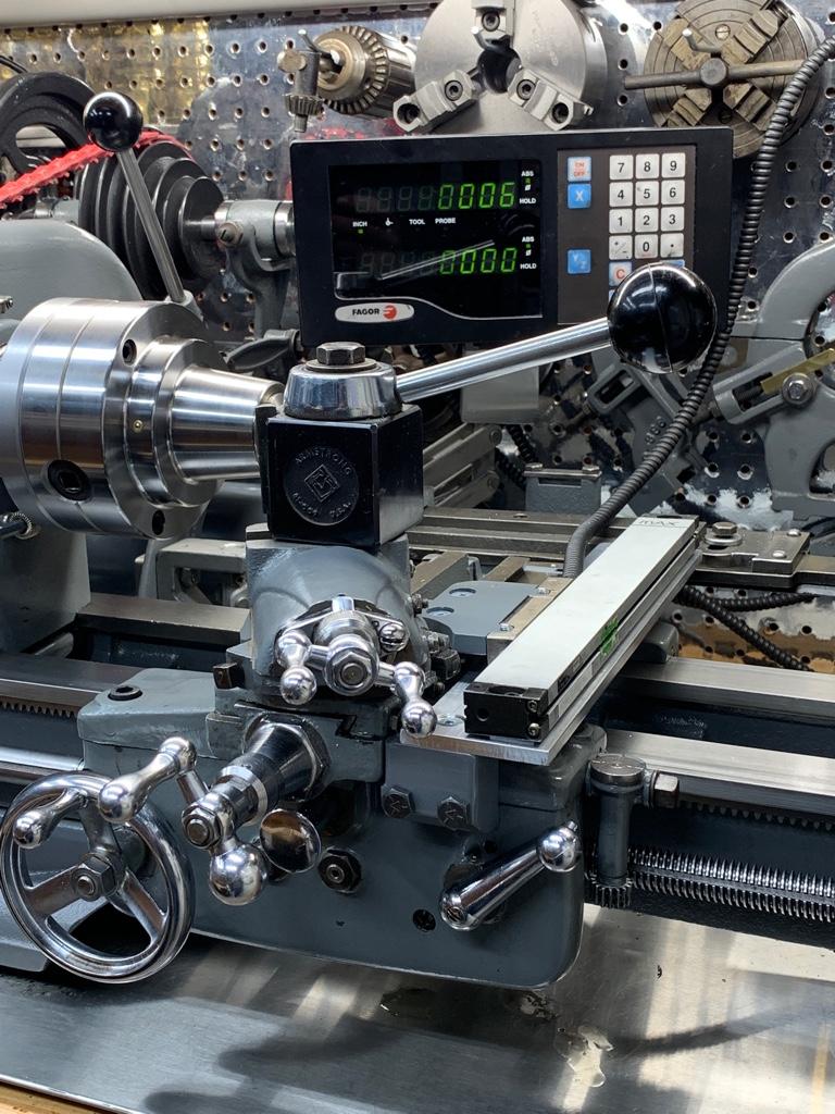
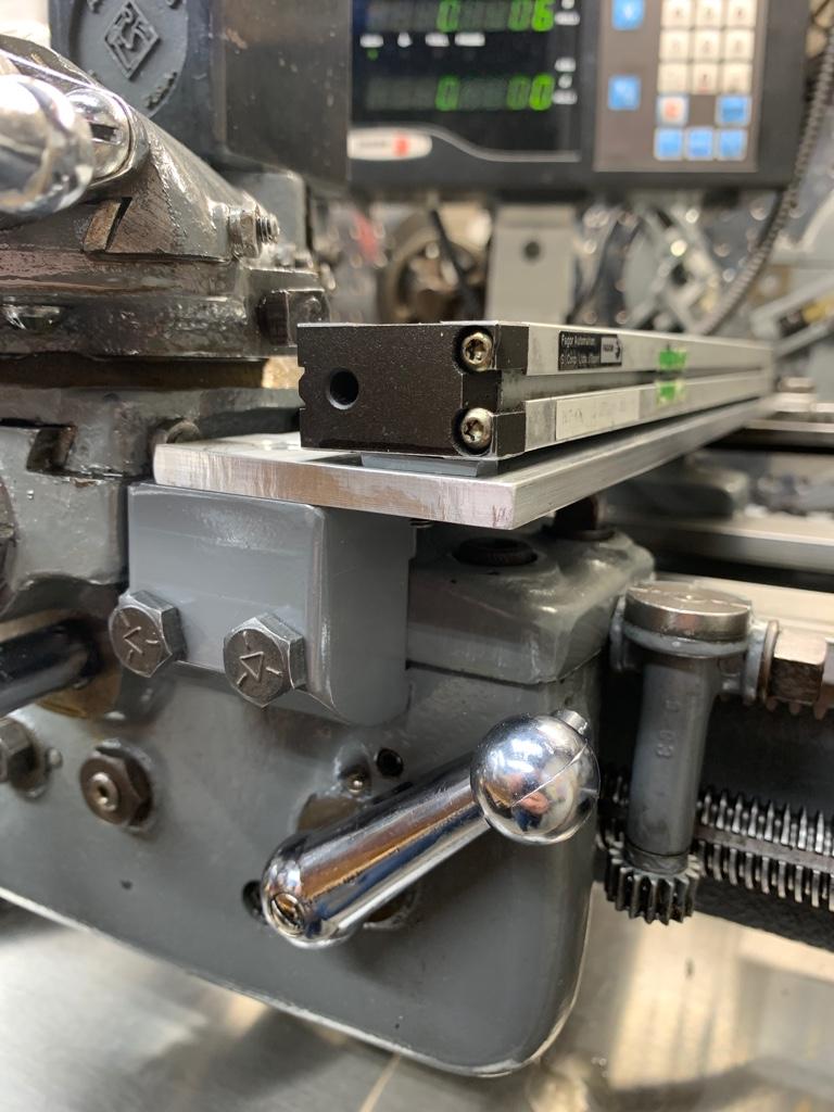
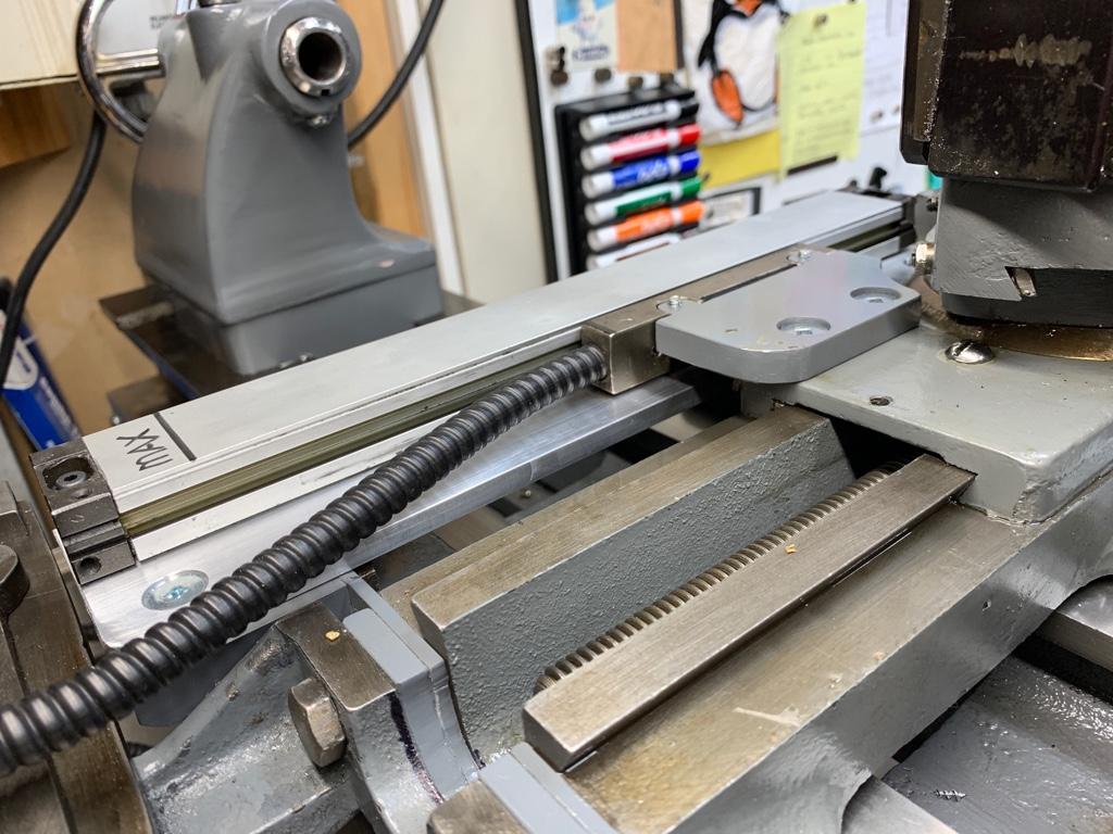
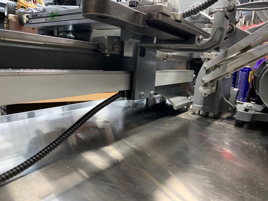
Mounting proved to be the next series of challenges which ultimately took the balance of my time and brain power. Quickly here is a description which will be followed by lots of pics. The mounting of the X axis was direct to the bed of the lathe and I used a piece of aluminum angle as the support/protection/mount. Other than arranging so that the read head would be accessible from a plate mounted to the saddle where the taper attachment mounts, it was fairly easy. The Y was significantly more challenging as I had to in essence fabricate a “flat” on which to mount...... that was out if the way, and still allowed all elements of the compound to work etc. In the end, the Y was mounted using 2 “affectionately referred to” precision crafted and fitted blocks and a piece of aluminum bar.
So I think it best to stop here and post a few pics and see where we go as I am becoming very long winded. I am pleased with how it turned out and am looking forward to using this DRO rather than occasionally seeing it when I open the cupboard where it was stored.
Thoughts, comments and criticisms are welcomed. And to those Atlas guys out there..... it CAN be done! I love my Atlas lathe, and I’m pretty sure I am now going to love it more.
Cheers All, pics to follow.
Derek.
Sent from my iPhone using Tapatalk
Last night I managed to complete what has been a long and arduous project that taught me a number of lessons; some of which I am happy to pass along this fine Saturday morning.
The DRO is a Fagor NVK-20. I purchased it about 4 years ago for $70 (CAD) at an auction. I had been looking through the auction listing online and saw the Unit. It was in an equipment auction and was notably “out of place” amongst the graders, loaders, backhoes, dump trucks etc. so I bid and ended up with it. Not until I went to pick it up did I find out that the glass scales came with it. “SCORE!”
One scale was 50”, the other was 19”. I watched any and all Youtube videos relating to cutting glass scales and decided my skillset and risk tolerance were not sufficient enough to attempt to cut them. Too, knowing how much a Fagor DRO costs new (I just bought an ACU-RITE 3 axis for my mill) the though of how bad I would feel if I screwed up precluded me from proceeding.
Along came Covit-19 and I was organizing, cleaning and re-jigging the shop. I came across the DRO unit and put it onto my bench...... I decided that it was time “**** or get off the pot”. The project took a full week of shop time but turned out reasonably, for a rookie.
My first issue was cutting the glass scales. This was not as challenging as first thought. In fact the first one only took about 10 min to cut. I used a Foredom (a big Dremel) cutter with a metal cutting disk to cut the aluminum around the glass, then a glass cutting “diamond” wheel to cut the glass. What I learned was that I needed to leave more supporting material (aluminum channel) before cutting the glass itself. When the fine folks at Fagor manufactured the glass scales, the piece of glass is supported along its entire length so it cut well and there didn’t seem to be any vibration issues causing cracks or breaks along the scale. After the cut I noted a small chip at the cut end which didn’t affect things in the least. I cleaned the scale with a blast of compressed air then got up inside with a blue paper shop towel moistened with 99% isopropyl alcohol and ran it full length. Both scales were cut the same way. It wasn’t until after cleaning the second one that it occurred to me that the blue shop towel might scratch the glass in some way, but it turns out that those scales are pretty resilient and even if I did scratch them to some degree, they are dead accurate.
The second scale when cut did crack about 2 inches in from the end. I’m not certain why because I took more precautions with it being closer to completion when it was cut. Fortunately because I was cutting the 19” in half (to fit the cross slide) I just used the other piece. I should add here that I cut, fitted and installed the X axis first before cutting for the Y (cross slide).
The cross slide required a great deal of thought. As anyone who owns one if these little Atlas/South Bend/Logan/Myford lathes, rigidity is often an issue. I needed a spot to mount the glass scale that was flat; which is nowhere on the Atlas carriage. I wanted to mill a flat on/into the saddle but was concerned that removing stock would affect rigidity. I “himmed and hawed” over placement, headstock side, tailstock side and settled on the tailstock side option. I wanted the scale to be protected from the headstock and the debris that comes from my repeated attempts to turn stock into chips. Further, the number of times I use my tailstock (and yes, this might be ignorance talking) is far less than what I’d have thought. And in most cases the reach will not be an issue. So tailstock side it was. I have really only lost about 2.7 inches, but if it was really necessary to do so, I can remove the apparatus; the slide can be removed temporarily in about 5 min.
Mounting proved to be the next series of challenges which ultimately took the balance of my time and brain power. Quickly here is a description which will be followed by lots of pics. The mounting of the X axis was direct to the bed of the lathe and I used a piece of aluminum angle as the support/protection/mount. Other than arranging so that the read head would be accessible from a plate mounted to the saddle where the taper attachment mounts, it was fairly easy. The Y was significantly more challenging as I had to in essence fabricate a “flat” on which to mount...... that was out if the way, and still allowed all elements of the compound to work etc. In the end, the Y was mounted using 2 “affectionately referred to” precision crafted and fitted blocks and a piece of aluminum bar.
So I think it best to stop here and post a few pics and see where we go as I am becoming very long winded. I am pleased with how it turned out and am looking forward to using this DRO rather than occasionally seeing it when I open the cupboard where it was stored.
Thoughts, comments and criticisms are welcomed. And to those Atlas guys out there..... it CAN be done! I love my Atlas lathe, and I’m pretty sure I am now going to love it more.
Cheers All, pics to follow.
Derek.
Sent from my iPhone using Tapatalk