Back at the well thirsty for knowledge

ltlvt

H-M Supporter - Sustaining Member
H-M Platinum Supporter
Joined
Aug 29, 2019
Messages
586
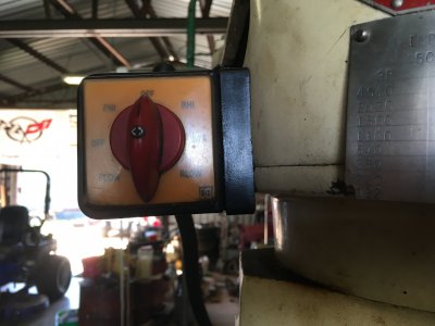
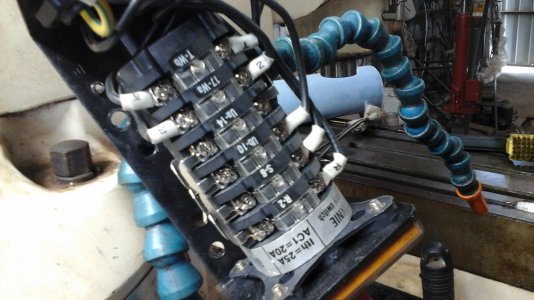
I have my McLane mill up and running with the Fugi Mini Series VFD. I am using a simple toggle switch for the FWD -OFF-REV It all works fine wired into control terminals of the VFD. I want to use the original Kannie Rotary switch that came with the mill to do the simple task the toggle switch is doing. The switch is for a 3 phase High and low speed motor so it Has Hi FWD Low FWD High REV Low REV 3 positions for OFF. I have went the route of trying to use an ohm meter to find a common and a FWD and a REV. I'm about ready to throw in the towel and just use the simple Toggle switch unless someone can throw me a bone on how these rotary cam switches work. This switch has 24 terminals with a hand full of jumpers I removed trying to find a simple FWD-OFF_REV, Thanks in advance. Here are a couple of just general pictures of the switch.
 

Attachments

  • IMG_1034.JPG
    IMG_1034.JPG
    305.5 KB · Views: 16
  • 20230316_143935.jpg
    20230316_143935.jpg
    749.9 KB · Views: 16
Last edited:
Normally with those you would need to jumper two of the poles together to create a double pole switch
For example you would jumper 1 and 3 together which would be your common, then 2 and 4 are the two forward and reverse contacts
What you have there looks like a 3-phase switch so the numbering is different. Probably you would need to use a ohmmeter and operate
the switch in both positions to find the two pole positions with respect to one of the jumpers
rotarysw12tblu.jpg
 
Last edited:
I would remove the rotary switch and direct wire the VFD output to the motor, otherwise you could just leave the rotary switch in the low speed forward position permanently and use a separate three way switch for VFD Forward/Stop/Reverse. The motor is a constant Hp, so you would connect the VFD outputs to terminals 1W 1U 1V and no connections to 2U 2V 2W. I would take a picture of the wire connections and wire labels before you remove everything. You then need to set the VFD maximum Hz to 120 when using the 4P Delta connection (1780 RPM), and at 120 Hz the motor will be running ~3580 RPM and from 60-120 Hz the motor will be making constant Hp.

You cannot use the current motor rotary switch for switching the VFD run commands as the contacts have increased resistance from switching the high voltage to the motor. If you want the same style of switch, you can get a 3 way maintained style (with two NO switch blocks) which would be ON Forward-OFF Stop-ON Reverse. You are using what is called 2 wire control, which requires a sustained on single to run, the danger is if the switch in in the run position on power up the motor will start. There should be a program parameter to prevent this, i.e. it requires the VFD input to be in the stop mode before it will accept a run command on power up.

1680189123541.png
 
Inside the the cover of any rotary switch I've wired (only a few) has been a schematic of the switching circuits.
Does your switch cover have such a schematic?
No it doesn't. I was hoping it did.
 
I would remove the rotary switch and direct wire the VFD output to the motor, otherwise you could just leave the rotary switch in the low speed forward position permanently and use a separate three way switch for VFD Forward/Stop/Reverse. The motor is a constant Hp, so you would connect the VFD outputs to terminals 1W 1U 1V and no connections to 2U 2V 2W. I would take a picture of the wire connections and wire labels before you remove everything. You then need to set the VFD maximum Hz to 120 when using the 4P Delta connection (1780 RPM), and at 120 Hz the motor will be running ~3580 RPM and from 60-120 Hz the motor will be making constant Hp.

You cannot use the current motor rotary switch for switching the VFD run commands as the contacts have increased resistance from switching the high voltage to the motor. If you want the same style of switch, you can get a 3 way maintained style (with two NO switch blocks) which would be ON Forward-OFF Stop-ON Reverse. You are using what is called 2 wire control, which requires a sustained on single to run, the danger is if the switch in in the run position on power up the motor will start. There should be a program parameter to prevent this, i.e. it requires the VFD input to be in the stop mode before it will accept a run command on power up.

View attachment 442890
Do you have a recommended switch, or should I just stay with the toggle switch? I also plan to put a remote Pot for the Hz. I already have a 10k pot that I have not wired in yet.
 
Normally with those you would need to jumper two of the poles together to create a double pole switch
For example you would jumper 1 and 3 together which would be your common, then 2 and 4 are the two forward and reverse contacts
What you have there looks like a 3-phase switch so the numbering is different. Probably you would need to use a ohmmeter and operate
the switch in both positions to find the two pole positions with respect to one of the jumpers
View attachment 442892
I did what you said to do and the switch is now doing exactly what I want it to do. Simple FWD OFF REV. Now just to remount the switch and wire it to the VFD. Next will be installing the remote POT for the HZ. The diagram with the Fugi Mini shows connecting the pot to the terminals 11-12-13 with 12 being the 10v+ so with that said I am assuming the center terminal on the POT (the wiper) should be connected to terminal 12 which is the 10v+ . Thanks so much for throwing me the bone on the switch.
 
You should not be using the current rotary motor switch to control the motor operation when connected to the VFD, I would recommend removing it. External speed pot has 3 connection 11 is the 0V potential, 12 is the sweep voltage, 13 is the +10V high side. Input 12 sweeps from 0-10V. To set the frequency control to the external pot. F01 = 1 (frequency command 1, voltage input to terminal 12) and C30 = 1 (frequency command 2, voltage input to terminal 12). To run the motor from the VFD inputs FOR and REV signal inputs program F02 = 1, this requires the 3 way external switch. CM is common connected to either FOR or REV input to activate that command.

1680223024198.png1680224245529.png

1680224771950.png
1680224959221.png
 
You should not be using the current rotary motor switch to control the motor operation when connected to the VFD, I would recommend removing it. External speed pot has 3 connection 11 is the 0V potential, 12 is the sweep voltage, 13 is the +10V high side. Input 12 sweeps from 0-10V. To set the frequency control to the external pot. F01 = 1 (frequency command 1, voltage input to terminal 12) and C30 = 1 (frequency command 2, voltage input to terminal 12). To run the motor from the VFD inputs FOR and REV signal inputs program F02 = 1, this requires the 3 way external switch. CM is common connected to either FOR or REV input to activate that command.

View attachment 442973View attachment 442990

View attachment 442995
View attachment 442996
Please explain why I should not use the rotary switch to control the FWD Off Rev . I am only using 3 terminals on the rotary switch and 3 terminals on the VFD FWD REV and CM. Thanks for the explanation on the POT wiring.
 
Back
Top