- Joined
- Feb 2, 2014
- Messages
- 1,072
I have a project coming up that requires me doing some ball turning for the handle ends.
I have made two different ball turners over the years and was not satisfied with either one. The first I made was mounted on the carriage and that one required me to remove the cross slide entirely to use it. The second was mounted in the quick change tool post but it was not very stable and hard to control.
Both of these designs had the same problems as the swivel handle was always in the wrong place or was hitting something. If you made the handle short enough to miss all the obstacles then you have little control over the cut. Also the ball size was limited by how much room there was between the turner base and the material or chuck. Neither was precision adjustable and setup was a job in itself. I searched through many designs and this is what I came up with and it is not original but does have some personal tweaks.
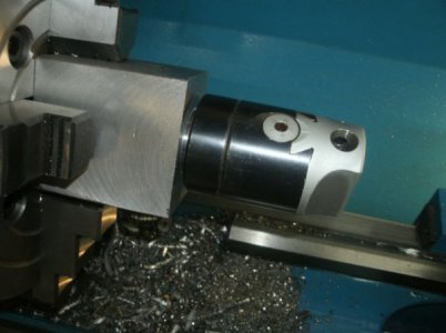
I have a boring head I use on the mill with an R8 shank so I would start with that but I still wanted it available to just put back in the mill for a job there.
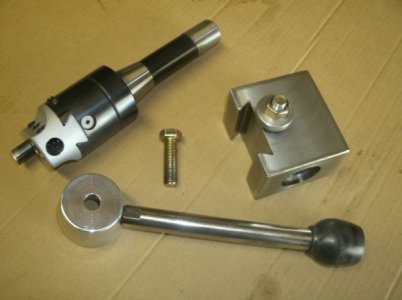
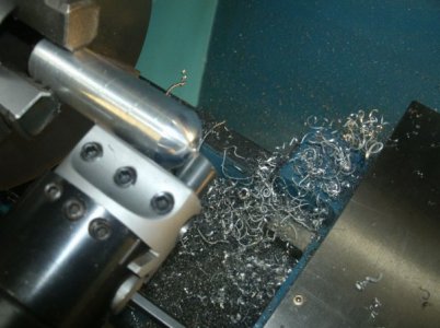
The parts and the first cutter I made from a ½” drill bit. It worked fine on aluminum but was not very good on steel turning.
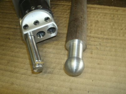
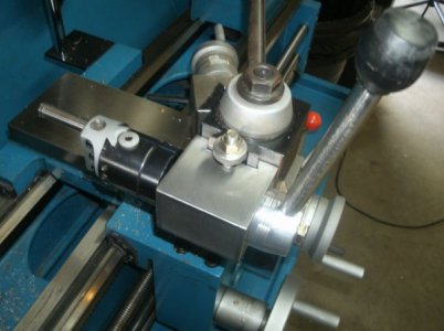
I used a carbide insert for the second design and the result on the steel turning. I have since modified the end clamp to more closely follow the insert shape and may modify the shank as well.
I now have a ball turner that is easy to control, is very accurate, greater capacity, and is installed or removed in a couple of seconds.
Thanks for looking
Ray
I have made two different ball turners over the years and was not satisfied with either one. The first I made was mounted on the carriage and that one required me to remove the cross slide entirely to use it. The second was mounted in the quick change tool post but it was not very stable and hard to control.
Both of these designs had the same problems as the swivel handle was always in the wrong place or was hitting something. If you made the handle short enough to miss all the obstacles then you have little control over the cut. Also the ball size was limited by how much room there was between the turner base and the material or chuck. Neither was precision adjustable and setup was a job in itself. I searched through many designs and this is what I came up with and it is not original but does have some personal tweaks.
I have a boring head I use on the mill with an R8 shank so I would start with that but I still wanted it available to just put back in the mill for a job there.


The parts and the first cutter I made from a ½” drill bit. It worked fine on aluminum but was not very good on steel turning.


I used a carbide insert for the second design and the result on the steel turning. I have since modified the end clamp to more closely follow the insert shape and may modify the shank as well.
I now have a ball turner that is easy to control, is very accurate, greater capacity, and is installed or removed in a couple of seconds.
Thanks for looking
Ray


