Band saw tension guage

Looking today at my gage stash I have a Mitotoyo Series 2 2416 SB. How's that for luck?

"Billy G"
 
Mark thanks for the post.
Bill thank for the link
I found a ton of great resource info there.

Definitely in the saved file.
 
OP is an interesting topic and ignited the idea for an alternate solution. I'm not sure it will work though :thinking:

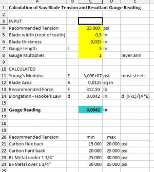
This is to make a temporary setup to measure the stretch with an extended tip dial indicator mounted on the blade to a reference clamp e.g. 5" down the blade. Or use a clamped caliper as in the article. Then measure the applied torque on the adjuster to achieve the desired stretch. This would allow for good repeatability. I've downloaded the Excel calculator that was linked to the article. I know the adjuster should be turned quite hard and will test if a fixed torque value will give the same stretch over and over again. If so, it will be easier to adjust the blade in the future.


Blade stretch calc.jpg

Blade stretch calc.jpg
 
Last edited:
I have been doing some research and a little experimenting with my Chinese band saw. I have made many modifications from all the posts on the internet and my saw works pretty good. It is an OLD, old, old Champion Machinery saw which is still the same castings as the new saws. I got mine a little over 10 years ago from an old barn. It was so dirty no one actually new what the pile of dirt was ( but I did). The owner gave it to me to get rid of it. Cleaning, more cleaning an did I mention cleaning fixed it up like new. It cuts square and straight but slow. I use good blades. With some education from the guy that makes my blades and a good bit of help from the Starrett company I have much improved the performance. I have been taught to look at the chips the blade spits out and determine if the speed needs upped or reduced and if the down force needs increased or reduced. All this turns out is really simple stuff, BUT I DIDN'T KNOW IT and now my saw works much better than it had. Now to the project. I use bi metal blades and my blade guy (and Starrett) said they need to be TIGHT! Blades up to 1 1/4 inch wide need to be 25000 to 30000 psi tension. They both told me to be in the low end to middle of that range to get optimum performance from my blades and saw. So I need to build a tension gauge as I am not laying out $300 for one. This project is costing me almost nothing as I had this small piece of aluminum plate lying around and I bought the indicator on "the bay" for $5 brand new ( what a find, this is an expensive indicator).

View attachment 88812 This is a simple project. It has three pieces, but a good bit of machining. The body and the lever arm which are made from aluminum and then the indicator. This photo shows the pieces all laid out and ready to machine. I am using a 2 1/4 inch diameter Federal indicator that reads each division as .0001". I got the print from the internet, but it was made for a mitutoyo indicator so I had to re calculate several dimensions to fit my indicator. I will post photos as I machine the parts.


Mark Frazier
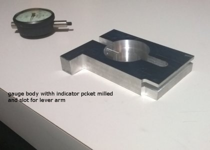

Ok.... I got half the machining done today. I will finish machining tomorrow and hopefully assemble.

saw gauge 1.jpg I turned the pocket for my indicator using the lathe and 4 jaw chuck
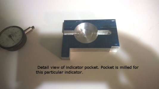
saw gauge 2.jpg I milled the lever arm slot and the slot for the indicator on my Burke mill
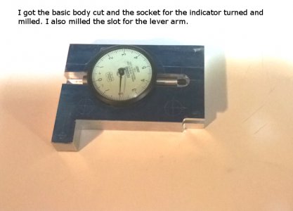
saw blade gauge.jpg Test fit and it is perfect. I will finish this block tomorrow.
Mark Frazier

Oh, here is the tension chart

iT IS CORRECTED ....this chart is only good for this gauge in this thread. (Billy G. , This chart works for the print you downloaded)


View attachment saw blade tension chart.xls


The tension gauge is finished and it does work. I really got into a groove machining and forgot to take pictures during the machining process, but it shouldn't be necessary since it is all just basic turning and milling.

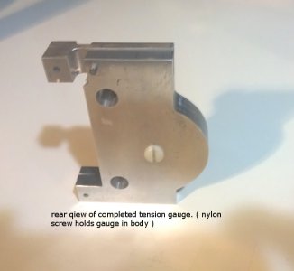
rear view of tension gauge.jpg This is a rear view of the gauge. The nylon screw holds the indicator securely in the body.
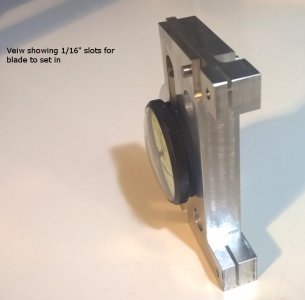
tension gauge slots view.jpg This view shows the 1/16" slots the blade fits in.
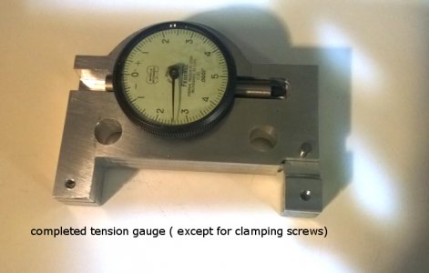
completed tension gauge.jpg This is the complete gauge (except for the clamp screws
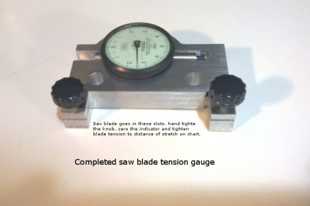
Finished saw blade tension gauge.jpg I found these really cool knobs. Now the SAW BLADE TENSION GAUGE is complete.

I am very pleased with the way this project turned out and now I can accurately set my blade tension. I learned a lot about sawing metal throughout this project and as a result my saw now cuts about three times faster and the cut finish is very smooth. my cuts are also extremely square too.

This project was very inexpensive to make.
1.) Aluminum plate 4" x 5" x.750 (1/2" can be used) ................ Found in my scrap box
2.) 2 1/2" diameter indicator reading in .0001" increments ....... $10 on eBay
3.) Fancy knobs for clamping screws ....................................... $4.00 at hardware store
4.) Nylon screw to hold indicator in place ................................. Found in my junk box

Total cost to build gauge ........................................................... $14.00

Cost to buy similar gauge commercially ........................................ $350.00

I can't complain about that! :joy:


Mark Frazier


A note to anyone making one of these. If you have a giant gauge like the one I used it is good as drawn. The lever arm is a 1.5:1 ratio so all the distances are 1.5 times greater than if the lever arm was 1:1. If you want the distances less and closer together, say because you are using a smaller gauge or for what ever reason, drill the pin hole for the lever at 1" instead of the 1.2" on the print. This will give a 1"1 ratio and the chart in this write up has to be changed accordingly.

saw gauge 1.jpg saw gauge 2.jpg saw blade gauge.jpg tension gauge slots view.jpg rear view of tension gauge.jpg completed tension gauge.jpg Finished saw blade tension gauge.jpg
 
Last edited by a moderator:
I just edited this thread and this project is completed. thank you for watching.


Mark Frazier
 
Well done Mark, well done.

"Billy G"
 
Nicely done, Mark. Nifty gadget.

Now you got me wondering about hacksaw blades...
 
Nicely done, Mark. Nifty gadget.

Now you got me wondering about hacksaw blades...

That is a good thought. I may have to put it on my list of things to research, but I got about a half dozen projects going at the moment .

Mark Frazier
 
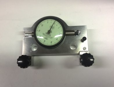
I made a modification to the band saw gauge. I drilled and reamed a 3/16" hole and put a pin made from drill rod in it ( put a little plastic cap on the pin for looks. the pin locks the lever arm and it was drilled with the gauge zeroed so now you clamp the gauge on the blade and pull the pin out. the gauge is zeroed and you make the adjustment. The pin keeps the lever arm from moving around when mounting the gauge and keeps it locked stable when in storage.

Mark
Band saw tension gauge 5.jpg you can see the black plastic handle on the pin on the right side of the gauge
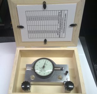
gauge in a box 1.jpg I put it all in a nice wood box

Band saw tension gauge 5.jpg gauge in a box 1.jpg
 
Mark, Excellent work and excellent thread.

One comment on the chart that you posted; the applicable blade width and thickness (back to root of tooth) are not specified. The tension load is quantified in PSI so the cross sectional area of the blade is a primary factor. The chart you posted can only apply to one blade size (one specific cross sectional area). The image posted by Micke S, in #13 above, illustrates a method to calculate the indicator reading for any blade cross sectional area to achieve the desired blade stress (tension).

I, for one, am going to save this thread for future reference. Again, thank you for bringing it all together.
 
Back
Top