Bob, I too would be interested in the CAD of that saw. Boy, would I love to pick your brain about building horizontals. From the pictures, I like that it is compact, mitering I think, variable speed, and homemade. Is that about a 1 ft. "throat?" What about the wheels, did you make those or adapt a part from a different application or purchase them as built bandsaw wheels. I myself am trying to keep the budget on such a build low so I thought maybe beefy 18" double V-belt iron pulleys and machine off the V part to the crossection design we are discussing, it is what i might use.. What if the saw fed completely horizontal onto the work instead of a tilted cut and finishing horizontal? I have to study the dynamics of metal removal in this manner some more. Maybe less efficient, I don't know yet. How large a diameter is the rotating support structure? Does it ride on bearings? Does it cut pretty accurately? I invite you to divulge more detail about the build and design considerations you went through arriving at this design. I must apologize for the disorganized order of questions, I was just excited by the design and style of your saw. Thanks for sharing!
-
Welcome back Guest! Did you know you can mentor other members here at H-M? If not, please check out our Relaunch of Hobby Machinist Mentoring Program!
You are using an out of date browser. It may not display this or other websites correctly.
You should upgrade or use an alternative browser.
You should upgrade or use an alternative browser.
Bandsaw Wheel Crossection
- Thread starter trg-s338
- Start date
trg,
Yes it miters from 0-60 degrees, and yes it's variable speed via a DC drive controller and 1HP dc motor.

If by rotating part you mean the pivot weldment, it's quite robust, with about 11 inches of wheelbase on the pivot shaft (7/8 dia tg&p) It all rotates (actually floats) on a film of grease on a ~7 inch dia plate guide by a king-post. Let's see if we can show this:

Wheels are ho-made.
The saw cuts very straight and square, in part due to the large wheelbase on the pivot. I'm sorry I don't quite follow your "what if.." scenario, I guess I'm getting dense in my old age!
I admit to having some trepidation about a design that twisted the blade 90 degrees, but it's proven un founded. Since 1997, Ive never had a blade break! The saw also pivots up to vertical.
Regards
Bob
Yes it miters from 0-60 degrees, and yes it's variable speed via a DC drive controller and 1HP dc motor.

If by rotating part you mean the pivot weldment, it's quite robust, with about 11 inches of wheelbase on the pivot shaft (7/8 dia tg&p) It all rotates (actually floats) on a film of grease on a ~7 inch dia plate guide by a king-post. Let's see if we can show this:

Wheels are ho-made.
The saw cuts very straight and square, in part due to the large wheelbase on the pivot. I'm sorry I don't quite follow your "what if.." scenario, I guess I'm getting dense in my old age!
I admit to having some trepidation about a design that twisted the blade 90 degrees, but it's proven un founded. Since 1997, Ive never had a blade break! The saw also pivots up to vertical.
Regards
Bob
Last edited by a moderator:
- Joined
- Jan 22, 2011
- Messages
- 8,031
I think he's thinking "What if it worked like a dual column saw?". Instead of the saw head falling from a pivot, falling straight down. That would be a more difficult design to pull off, it would seem.
Thanks for the additional info on your saw. Indeed having a gliding surface for the miter pivot makes for a simpler and less part count, less complex and maybe even less unwanted play in the assembly. If I may ask, it is not apparent to me how you maintain the twist for perfect alignment. Does the two bearings on both flat sides and the back edge do it alone? Any provision to adjust the alignment of the blade? What is the diameter of the wheels? How did you make them? Also, there does not seem to be much of a tilt to the wheels relative to the blade--an effort I think manufactures use to reduce the amount of twist in getting the blade vertical.
Yes, Mr. Wells has expressed what I meant in presenting the saw to the work. I seems it would make it convenient in knowing exactly where the edge of the cut would be and visualizing the cut before it starts.
Yes, Mr. Wells has expressed what I meant in presenting the saw to the work. I seems it would make it convenient in knowing exactly where the edge of the cut would be and visualizing the cut before it starts.
trg,
Twist in the blade is maintained by the bearings alone, I toyed with the idea of adding carbide guides like a DoAll, but didn't for a couple of reasons:
1. Saw cuts great as it is.
2. You need to run coolant for carbide guides, and I don't like the mess.
It's not apparent, but the plane of the guides is adjustable by tilting the ground bar that the guide arms slide on. This is a tedious adjustment that only needs to be done once. Must be set up parallel in a couple of planes to the wheels, which are set coplaner with a blade under tension. There is no tilt to the blade--as I said before, it is twisted 90 degrees. Stress due to twist can be minimized by controlling the distance from the guide to the blade tangent point on the wheels. Another good reason to keep the guides close to the work.
Wheels are about 9 inch diameter. This is a 1/2 inch blade version of the saw. Never a problem with blade fatigue using .025 in thick blades. Your proposal to use 18 inch wheels is appropriate for .042 in thick blades, such as 1.25 wide. Biggest I've built used 14 inch wheels to run 3/4 x .035 bimetal bands. Wheels are machined from heavy wall tube, and bolted to fabricated plate/hub assemblies.
I did once noodle a design for a linear feed saw like a dual column, but using a single massive column with bearing surfaces spread about 8 or 10 inches. Would have been fun to build, but overkill for a hobby shop! The saw I posted above, cuts about everything I want to cut. If you need big capacity--go for it! If you have the tools to do the building of the larger saw, it's really no more work than a small one like mine. My hobby has evolved into areas that don't require a great big saw--that's why I built this one!
Hope I've answered your questions!
Regards
Bob
Thank you sir for your perspective. I am still toying with the wheel size. I am considering wheel size for the purpose of increasing throat depth for use when upright used as a vertical band saw and adapted removable table, as well as the increase span which may reduce blade twist tension, not to speak of the added stiffness of a wider, thicker blade at the cost of increased kerf size and waste. You have helped clarify many of my vague, blurred ideas about the horizontal band saw idea.
I guess I will be the "turd in the punch bowl" here. First let me say, I design tooling, fixtures, special function machines and devices for the medical device industry. I am a 14 year user of Pro-e and SolidWorks CAD.
Your saw is very ingenious and a fine job of fabrication.
Now here is the "turd" part. I only have time to accomplish a limited number of things in my life, especially as I get older. I use to say "I can restore that, fix that, rebuild that, design that, etc. I pick and choose more carefully what I work on these days. I no longer have time to build a machine that I can buy for probably less money than I can make it for. I have rebuilt quite a few machines over the years and have a pretty well equiped home shop. I now value my time a lot more than I did when I was much younger.
Looking back, I wish I had spent more time on projects like this.


Charlie W.
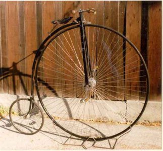
In case you are interested, I built this when I was a teenager on my first lathe. Logan 200
Your saw is very ingenious and a fine job of fabrication.
Now here is the "turd" part. I only have time to accomplish a limited number of things in my life, especially as I get older. I use to say "I can restore that, fix that, rebuild that, design that, etc. I pick and choose more carefully what I work on these days. I no longer have time to build a machine that I can buy for probably less money than I can make it for. I have rebuilt quite a few machines over the years and have a pretty well equiped home shop. I now value my time a lot more than I did when I was much younger.
Looking back, I wish I had spent more time on projects like this.


Charlie W.
In case you are interested, I built this when I was a teenager on my first lathe. Logan 200
CharlieW,
I can certainly appreciate your point of view, and I certainly wouldn't consider you a "turd" for it. I spent 35 years as a mechanical engineer and machine tool designer starting off on the board, and graduating to my first CAD system (Computervision Cadds 3) in 1979. Used several different systems since that time. I've also been a hobby machinist longer than that! For me personally, the thrill of the hobby comes from designing and building my own machines--it's not for everybody. Yes, I do my share of rebuild and repair of just about everything. I'm also a woodworker. The important thing is to do what gives you joy! It's a hobby after all, it's supposed to make you feel good! I was blessed in having a job that I loved (most of the time), it just so happened to dovetail nicely with the hobby that I love. Retired from the job, not from the shop!
Thanks for the compliment on the saw, likewise a great job on the velocipede. I doubt that my skillset as a teenager would have allowed me to build anything like that!
Regards,
Bob
Thanks Bob. I agree about doing what is fun and challenging. I have a few more years to go before I can retire. Keep posting your project pictures. I love seeing what others build and their inovations.
I was about 18 when I started on that Bike and 19 by the time I finished it. I was a little more than a novice machinist then. I had plenty of questions and spent countless hours working on it.
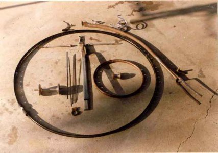
The tire is called "cab rubber" and is much like a thick-walled hose. It is about 1" in diameter and has about a 1/4" hole going through it. The tire lays around the rim and overlapps about 5". A 1/8" dia. wire is inserted inside and tensioned to where the tire is compressed until it hugs the rim. and the ends are fastened together. The rubber is worked over the joint until the ends of the tire meet.
This is me waaaaay back when I first built it. Ah...To be young and thin again.

Charlie W.
Who can guess where this picture was taken? Hint: The place is famous in south east Michigan.
I was about 18 when I started on that Bike and 19 by the time I finished it. I was a little more than a novice machinist then. I had plenty of questions and spent countless hours working on it.
The tire is called "cab rubber" and is much like a thick-walled hose. It is about 1" in diameter and has about a 1/4" hole going through it. The tire lays around the rim and overlapps about 5". A 1/8" dia. wire is inserted inside and tensioned to where the tire is compressed until it hugs the rim. and the ends are fastened together. The rubber is worked over the joint until the ends of the tire meet.
This is me waaaaay back when I first built it. Ah...To be young and thin again.

Charlie W.
Who can guess where this picture was taken? Hint: The place is famous in south east Michigan.

