-
Welcome back Guest! Did you know you can mentor other members here at H-M? If not, please check out our Relaunch of Hobby Machinist Mentoring Program!
You are using an out of date browser. It may not display this or other websites correctly.
You should upgrade or use an alternative browser.
You should upgrade or use an alternative browser.
Bearing Ball with Flat for Vise work...?
- Thread starter EmilioG
- Start date
- Joined
- Dec 18, 2014
- Messages
- 11
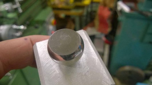
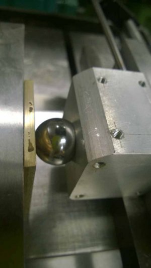
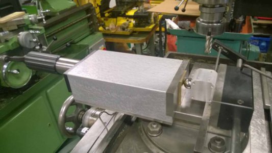
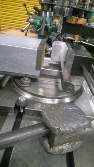
Hope these pictures show how I use mine. The clamping force of my Aciera hydraulic vice is over 2 metric tons according to the manual and that does not visually dent aluminum surfaces. The ball in the pics has 16 mm flat intended for soft materials. If I ever make new ones, I would use 25 mm (1 inch) balls.


- Joined
- Apr 4, 2016
- Messages
- 854
Great! Thank you Isberg.
Now, enlighten me some more. Why use the ball?
Insures that parts that don't have parallel sides will maintain proper contact with the stationary jaw of the vise.
Ted
- Joined
- Apr 12, 2011
- Messages
- 3,475
Insures that parts that don't have parallel sides will maintain proper contact with the stationary jaw of the vise.
Ted
Thanks Ted,
I thought that the movable jaws provided for this? Along with the complimentary persuasion of a hammer upon clamping for proper seating of the part against the stationary jaw and parallel. Also, if it was needed wouldn't this be a standard practice? Sorry, I am not seeing the need for the added complexity. But hey, it is just me.
- Joined
- Jul 20, 2014
- Messages
- 1,386
I would indicate the part to check how well it stays fixed. This problem is another reason why I would like to buy a precision screwless vise.
A larger one, not the tiny 2" vises but something like a Wilton. Fairly expensive but you're paying for precision. Also, take a look at the Quadralel device.
Very interesting design for larger work. The other tool on my wish list is a vintage Murkens cylindrical square to check the work, tools and machines.
RandyM's concern is valid. Sometimes a dead blow and/or a piece of aluminum wire is all that is required.
- Joined
- Apr 4, 2016
- Messages
- 854
Randy,
Any "quality" vise should maintain parallelism of the movable and stationary jaws. In other words, the movable jaw should not deflect at all. Also, it kind of is "standard practice" to use some method such as this when clamping irregular parts in the milling vise. Some folks use things like a piece of copper wire or brass rod against the movable jaw to accomplish the same thing.
Ted
- Joined
- Dec 18, 2014
- Messages
- 11
@RandyM I´ll try to explain my understanding of how it works in the pictured setup, please excuse me if I state some obvious facts trying to rationalize this:
The ball allows You to easily find the best spot for pushing the work piece well against the fixed jaw, which is my reference. It also helps clamping tapered and uneven stuff more securely by taking upp angular errors. For really rough stuff I still prefer the old Al-wire method or Al scrap instead of flattened balls.
Indicate the back jaw and the bottom of the vice for reference as usual. If I clamp something non square in the vice now it can be square either against the front or back jaw but not both at the same time. Assuming the vice jaws stay parallell. The ball will then make it possible for the work piece to freely to rotate against the movable jaw. Therefor the work piece will be referenced to the plane of the back jaw only. The polished flat on the balls makes it possible to clamp hard without denting stuff. Especially useful for Al and soft stuff.
I usually tighten the vice a little and then nock down the work piece with a plumbob against the bottom parallell under the fixed jaw. When the vice is tightened the work piece should be quite parallell to both the bottom of the vice and to the fixed jaw. If the bottom and back of the work piece are already at right angles, use 2 parallells. If the back and front of the work piece are already parallell, don´t use the ball, just use the vice jaws.
Hope this makes any sense at all... Erik
Last edited:
- Joined
- Dec 20, 2012
- Messages
- 9,422
Thanks Ted,
I thought that the movable jaws provided for this? Along with the complimentary persuasion of a hammer upon clamping for proper seating of the part against the stationary jaw and parallel. Also, if it was needed wouldn't this be a standard practice? Sorry, I am not seeing the need for the added complexity. But hey, it is just me.
Randy, Ted, please allow me to expand on this for the benefit of the new guys. The ball or round rod is typically used for the initial squaring of a work piece but it can also be used to hold something with off-parallel sides in the vise. It is especially useful for initial squaring though, and the rougher the work piece the more important it is to use it.
When we square a work piece we are looking to create a master face from which all subsequent sides will be referenced, right? Typically, this is the first face we cut and we then want that first face to be absolutely flat against the fixed jaw of the vise. If the face opposite this reference face is not square it can cause the work to tilt or angle as the vise is tightened and pull that reference face away from the fixed jaw. The ball/rod prevents this by allowing the work to tilt and align the reference face to the fixed jaw while still allowing the vise to clamp down solidly. Normally, we use the ball for the first three passes, after which we will have square sides in contact with the bed of the vise and both jaws. Then we remove the ball/rod and cut the fourth face and ends to finish squaring the work.
This may not be standard practice for everyone but it is the only way I know of to accurately square a rough work piece in the vise.
- Joined
- Dec 18, 2014
- Messages
- 11
For a good video intro to squaring stock I recommend watching
This Old Tonys You Tube video "Stock? Mill? Square!"
Mikey, I believe the method You describe pretty much is the standard method for squaring stock in the mill, at least its exactly the way I was thought to do it long time ago...
Erik
This Old Tonys You Tube video "Stock? Mill? Square!"
Mikey, I believe the method You describe pretty much is the standard method for squaring stock in the mill, at least its exactly the way I was thought to do it long time ago...
Erik

