Bearing preload

for your arrangement, with respect, i would suggest these...
use these in opposition, on both ends (or not)


McMaster Carr 94065K32
 
Last edited:
for your arrangement, with respect, i would suggest these...
use these in opposition, on both ends (or not)


McMaster Carr 94065K32
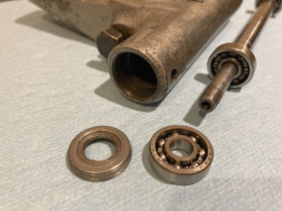
The threaded retainer for the bearing largely matches the outer race of the bearing.

Bearing retainer.jpg

That makes me think that the washer with spring fingers is a better design for this application than the Belleville style that you linked to. No? Is there a reason that the Belleville style would be superior?

My thinking is that the shoulder to shoulder length of the spindle needs to be a few thous longer than the shoulder to shoulder length of the interior of the casting. That way, the shoulder on the spindle will press against the inner race which will press the balls against the outboard side of the valley of the outer race. The outer race will push against the spring fingers and have a small amount of 'give' to take up differential expansion.

One spring washer or two? I have no idea. I'm probably going to have to order a pack of 10 so I can try it both ways. OTOH, the threads are a little buggered up on one end of the casting and there is not an excess of available space. So we'll have to see.

On yet another hand, this tool post grinder was a basket case when I bought it (for $5). I'll only use it occasionally and never for an extended period of time. (IE maybe grind some chuck jaws or similar.) BUT, the spindle turns at up to 16,000 rpm so I don't want to have anything *exciting* happen if I'm using it. Therefore I'm not concerned about getting this perfect but I do want to get fairly close.

Craig
 
although unlikely, the fingered design has a problem.
if there was to be finger separation , at 16K rpm's i wouldn't want to see the end result

i have yet to see belville springs break, not sayin that they don't break.
 
I think there is more going on inside the original than simple belleville washers/whatever.

In the care manual you linked it states that when cold the shaft should feel tight but after warmup it should be free spinning.

I've been trying to see if there might be some collars or anything else with dissimilar materials that would make the shaft effectively shrink slightly in comparison to the housing but nothing is jumping out at me at this moment.

Edit: it probably pinched the inner races against a "too short" shaft so when it heats up it releases some of the preload.

Sent from my SM-N975U using Tapatalk
 
Last edited:
The spindle that was in the grinder when I got it is bent. I'm sure it is user-made rather than original.

After some poking around that may very well be an original. Is yours just a 2 speed (only 2 pulleys)?

Looks damn near identical to the series 14 which only has 2 speeds & the exploded view can be seen here:

Picture posted above in the thread appears to be a series 44 with an exploded view here:

They look pretty different but it appears that preload is dealt with in the same manner using a "double back to back" arrangement. Use of thrust washers is a dead giveaway that the bearing caps are loading the inner races, not outer. Wave springs on one side allow the cap to lock the inner race in position on the shaft but exert force on the outer race through the spring instead. So that's the axially floating side & the other locks both axially & radially.

I hope this helps!


And another edit!

I'm in socal fairly close to McMaster so I get stuff pretty quick & I could drop it in the mail to you. Don't know if 2 reasonable shipping costs could add up to the ridiculous rate McMaster charges for Canada, but it's an option if you'd like!

Regards,

Steve
 
Last edited:
After some poking around that may very well be an original. Is yours just a 2 speed (only 2 pulleys)?

Looks damn near identical to the series 14 which only has 2 speeds & the exploded view can be seen here:

Picture posted above in the thread appears to be a series 44 with an exploded view here:

They look pretty different but it appears that preload is dealt with in the same manner using a "double back to back" arrangement. Use of thrust washers is a dead giveaway that the bearing caps are loading the inner races, not outer. Wave springs on one side allow the cap to lock the inner race in position on the shaft but exert force on the outer race through the spring instead. So that's the axially floating side & the other locks both axially & radially.

I hope this helps!
Thanks for looking at this but I think my old Series 14 grinder is rather different from the modern ones--mainly due to lubrication. Mine has a Gits oiler in the center of tube casting as is pictured in the Care & Operation manual [1]. I believe the modern ones must be using sealed, lubricated for life bearings. With the arrangement of parts shown in the modern parts list, I don't think oil could flow effectively through to my open bearings. Sealed bearings are about 0.063" wider than open bearings and there is so little room in the bearing housing that I don't believe sealed bearings would fit. Too few threads on the bearing cap would be able to engage. So I think there must have been a bit of a redesign whenever they switched to sealed bearings. Mine is designed so that lots of oil passes through the bearings regularly to keep them lubricated while flushing away grinding debris.

Unfortunately I can't find a parts diagram that relates to mine.

Re the bearing caps loading the inner races, wouldn't that create massive friction? The bearing caps are not spinning but the inner race is spinning (and up to 16,000 rpm). Thus if the spring pushes between the bearing cap and the inner race, it must be sliding against something, creating friction. That's why I thought the spring washer must be pushing between the outer race and either the bearing housing or the bearing cap. All of those parts are stationary. Am I missing something?

Craig
[1] See p. 10 of the C&O, which is the 12th page of the pdf.
 
On the "44" the spring washer goes between that inner screw-in piece (#34) and the bearing outer race. There is then a threaded cap (#28) on the outside that pushes against the outer race and creates the preload. The purpose of the spring washer is to make it harder to screw in the outer cap, so that it does not loosen up with use. The amount that the outer cap is screwed in is what sets the actual preload.

The teeth on that inner screw in piece (#34) are accessible using a jeweler's screwdriver in an access hole that has a screw in plug. There is also a setscrew with a brass plug (or was it a separate innter set screw?) that is used secure the inner screw-in piece.

Hope that makes sense...
 
Edit: dang you Tapatalk!! A notification would have been nice when @machPete99 posted that great info!!

Good stuff Pete, thanks!

. So I think there must have been a bit of a redesign whenever they switched to sealed bearings. Mine is designed so that lots of oil passes through the bearings regularly to keep them lubricated while flushing away grinding debris.

Unfortunately I can't find a parts diagram that relates to mine.

Doh!!

I actually read that the series 44 was the only one of their products not using a sealed bearing setup. Then I came across photos of the series 14 & got so excited that I found a match that I must have just pushed the sealed/open bearing issue straight out of my head.

Re the bearing caps loading the inner races, wouldn't that create massive friction? The bearing caps are not spinning but the inner race is spinning (and up to 16,000 rpm). Thus if the spring pushes between the bearing cap and the inner race, it must be sliding against something, creating friction. That's why I thought the spring washer must be pushing between the outer race and either the bearing housing or the bearing cap. All of those parts are stationary. Am I missing something?

Craig
One of their manuals stated that temperatures as high as 55° celsius above ambient is normal so there's a ****-ton of friction somewhere.

Buuuuuuuut........................

I'm batting a thousand today when it comes to brain farts.

There's no freaking way it could work the way I described. A 10" steel shaft will grow by .00715" with a 55°C temp rise & if the end caps were in any kind of contact with the inner races through thrust washers/spacers/even a thrust bearing, there's no way in hell the spindle would exhibit the expected cold/tight spindle => warm/free running spindle behavior that is noted in the care/use manual you've linked.

After some r&r for my brain, squinting at exploded views/pictures, and doing some sketching, I think I have it (mostly) figured out. I was missing the fact that when fully assembled with pulley & wheel the inner races become solidly locked onto the shaft against the shoulder.

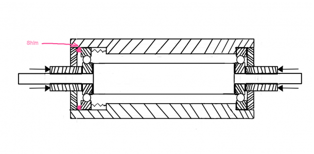
Here's a sketch I came up with:

Pulley side in the left & wheel side on the right. Just not sure what, if anything, is going on between the end cap & bearing on the pulley side, especially with your model.
f3646cad714470f7c924a52d4087eaa9.jpg


Sent from my SM-N975U using Tapatalk
 
Last edited:
You may need to have some shim washers in the area in red. I think I had to add them on my 44 in order to get things aligned properly.
Even still the left hand end cap will determine preload. You just need to tighten until there is slight drag on the spindle and no detectable axial play.
If the spring washer is not pushing back you may need shims in there too.spindle_shim.png
 
Back
Top