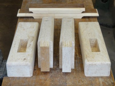
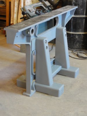
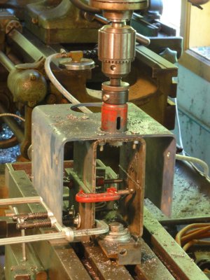
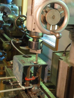
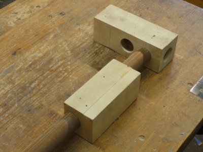
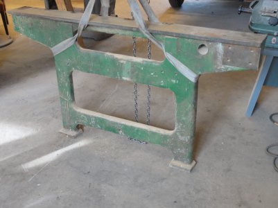
The casting for the machine base was once part of a production clamp used to assemble wood window sash. I grabbed a pair of these on their way to the dumpster thinking they would someday be the perfect base for something: straight, stiff, stable, and right at waist height.
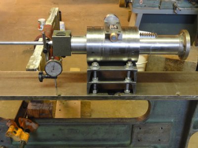
I’ve laid out the location for 4 holes to be drilled and tapped to anchor the quill to the base.
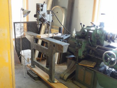
I was really pleased with how solid the quill felt after it was bolted to the machine base. I set an indicator on it to tram the base and was surprised when it trammed true on the first try. I did go to some lengths with this in mind, but I’d have to say I got lucky here.
The motor is 1 ½ hp, 3500 rpm, 3 phase. It weighs a ton, so it can’t just hang off the back end of the quill. It will ride on a trolley made out of a piece of ½” aluminum plate with some small ball bearings as wheels. The plate has a couple of grooves cut in it that register on the motor’s cooling fins, and the bearings are placed to have clearance under the motor.
I pulled the motor apart to reverse the end housings so the electrical box would be on the back side away from the operator. Inside, the front bearing, with a zerk fitting, was encased in a ball of grease. The back bearing, with just an access cover, looked like it hadn’t been lubricated since it was built 50 years ago. I cleaned one and greased the other, and they both seem to turn fine.
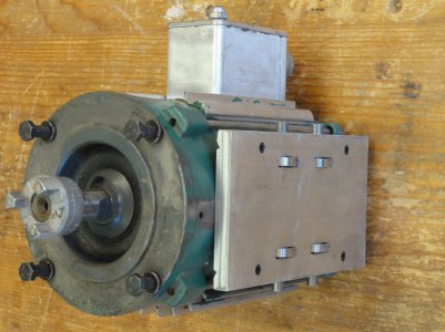
I was less lucky with the motor alignment. For starters, I’d built in a slight twist; so the motor trolley wouldn’t sit evenly side to side on its track. I had to elongate the bolt holes in this coupling between the motor and quill about 3 degrees on the rotary table.
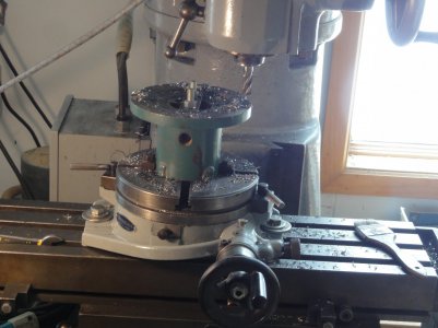
The motor trolley track is supported by the last cutoff pieces of the 6” channel iron. There was a high spot in the middle that the motor would not roll over, and it took several trial-and-error cuts to trim down the center supports before the movement was smooth end to end.
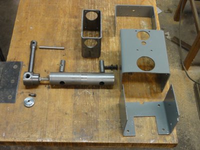
I spent the most on the electrical components. I rummaged through my old switches, but they looked and felt clunky. I thought the machine was looking coherent for an assembly of odd parts and spent some time picking and choosing a starter and enclosure that fit in visually.
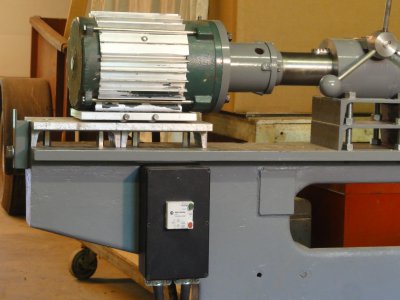
Now we’re getting to the business end of the drill. The long travel and high spindle speed would whip the drill around without a support bearing close to the workpiece. I bored and reamed the bushing on the right using the ground shank of an R-8 collet as a bore gauge. It’s just under 1” diameter, so it should work with the smallest drill I plan on using. Then I used the R-8 collet like a mandrel to center and align the bushing in the lathe chuck. I turned the o.d. to 1.375” to fit the bearing and threaded it 16tpi for the retaining nut on the left.
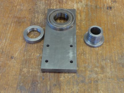
I bored the support column for the bushing bearing on the lathe faceplate. I started out with a longer piece than needed so I could clamp it on both ends and for balance. Originally, I planned to cut off one end and bore the cut piece to make a clamshell housing for the bearing, but this is one of the best fitting bores I’ve ever made. The bearing tapped into the bore and refused to budge, so I decided to use it as it looks in the previous picture. I’ll see if it holds up.
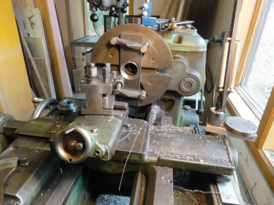
The drill extension is a critical turning. I center drilled a 1” cold rolled rod both ends and set it between centers to true it end to end. Then I switched back to the 4-jaw chuck, centered it again, and recut the centers for a true alignment. At the same time, I drilled and reamed the drill end to 3/8” to hold the drill shanks. I’ll be using carbide tipped Forstner bits. I think the 3500rpm spindle speed would burn hss drill bits at the larger diameter. Back between centers, the chuck end was turned down to 5/8” with the very tip down to ½”. The tip will pass through the chuck, which has an open back, and into a centered bore in the spindle itself. With the drive dog on the chuck end, the extension is ground in a single pass end to end until it is a slip fit in the bushing. The compound is set to 60 degrees so the radial infeed is half the compound feed. There has to be just enough friction in that fit so the bushing will rotate with the drill extension as it passes through it. I expect a really serious person would heat treat this piece, but that is beyond me.
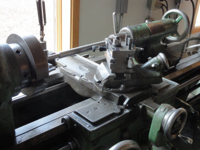
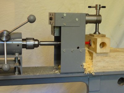
Everything is lined up to locate the bolts that will fasten the support bearing to the base. The quill moves easily through its full travel. The drill extension turns without binding, and the bushing turns with it all the way also. I did need to set some paper shims into the chuck to center the drill extension. Headstock chucks are a bit of a puzzle to me. They just have a single hole for a chuck key, and I wonder if this one is worn unevenly because of that.
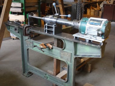
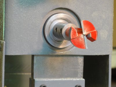
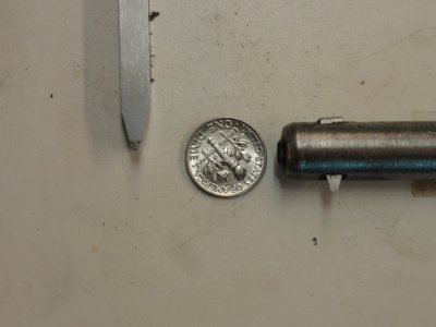
I’m starting with a 1 ½” drill. The drill is advanced a bit to show the set screws that secure it.
