- Joined
- Nov 7, 2021
- Messages
- 12
Hello all,
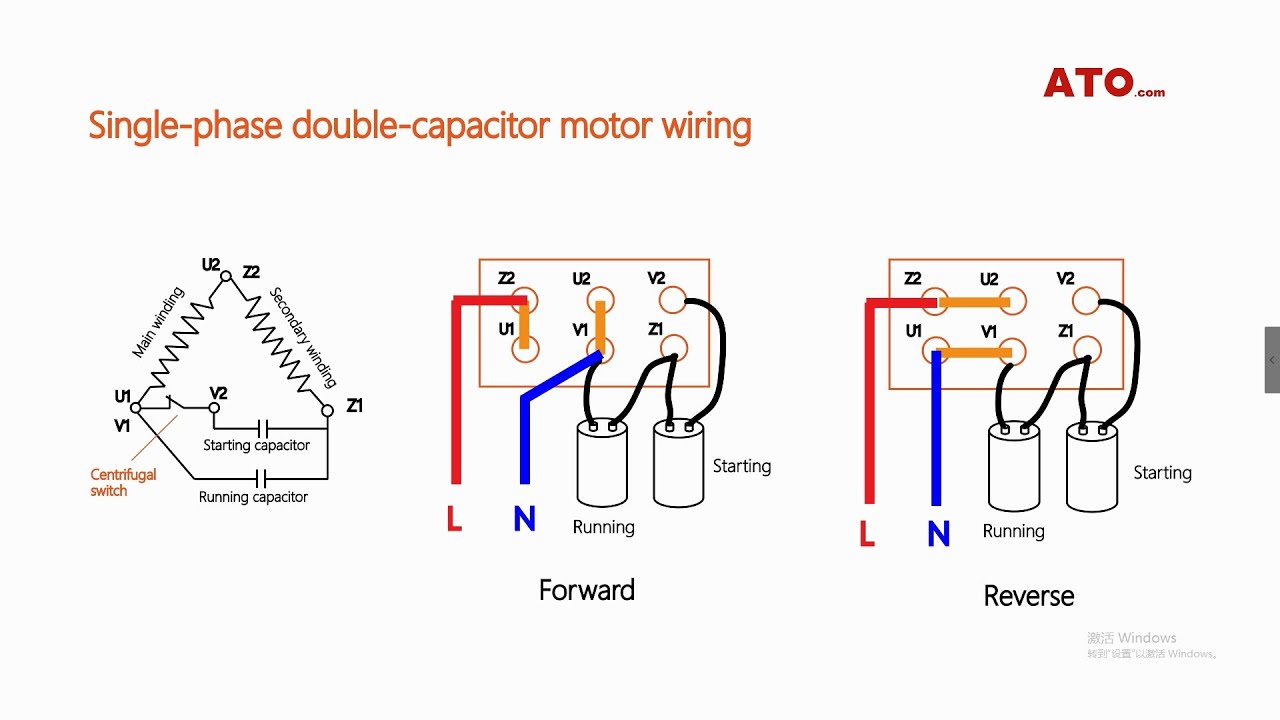
TLDR electrical dunce can’t figure out how to wire the lathe to have forward and reverse rotation.
I have a Birmingham ct-1440g lathe. Taiwanese made and effectively a rebadged version of every other Brand out there. I’ve had the machine for about a year and recently decided to mount to lathe to the floor. It’s currently on adjustable rubber feet and it’s not rigid enough for the turning I’m starting to get into. Along with bolting to the floor I’d like to actually level the machine. When I got the machine it had no plug wire. Currently wired for 220v. According to the induction motor cover plate diagram the only way to get it to run reverse is by physically changing the location of the capacitor wire in the control box which is on the back of the machine and will be against a wall which will be a struggle to get to when the machine is bolted to the floor.
I’m not sure if I can post pics yet as I haven’t posted 3 times yet, but certainly can to show what I’m working with. I’ve searched a lot for info on this particular machine and come up pretty empty. It is different enough to all the other machines that I can’t get accurate enough info to tell me if it’s possible. And I suck when it comes to electricity and I cannot figure it out myself. I’m usually a try and do it yourself to learn but, this one I just can’t.