- Joined
- Mar 22, 2013
- Messages
- 215
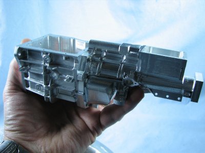
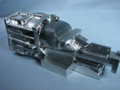
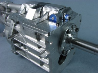
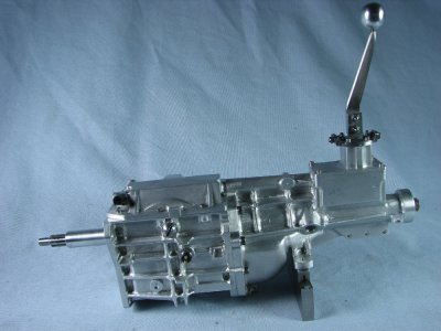
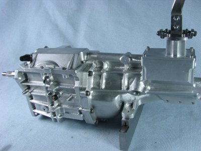
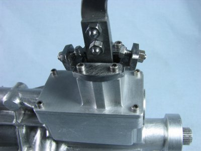
As a follow up to the thread I started on my 302 V-8 engine I am posting this abbreviated thread on the building of the T-5 transmission to go with it. Each fall I somewhat plan out what my projects will be for the forthcoming winter season. Having just competed 5 hit and miss engines for someone else I was ready for a change. My sons have always been into cars and while visiting one day I noticed a T-5 transmission laying in the corner. This transmission happened to have come out of a Mustang but similar units are used in many other automobile brands but with different ratios and tailshaft extension. I thought this would be a good project and eventually I could bolt it up to my engine.
I lugged the trans home and went online to see how they came apart. There was a very comprehensive maintenance manual online which helped tremendously. I proceeded to dismantle the transmission and make dimensioned sketches of all the parts. These sketches were later turned into Autocad drawings.
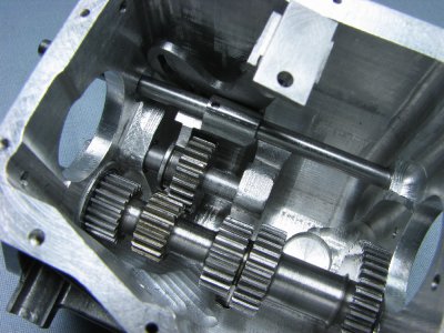
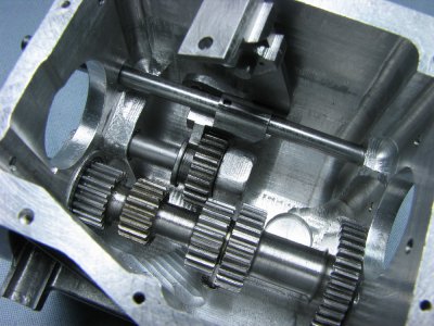
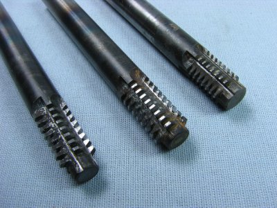
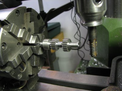
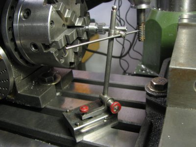
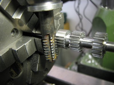
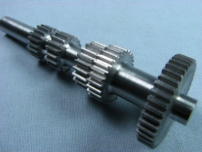
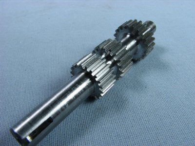
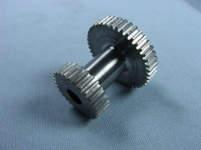
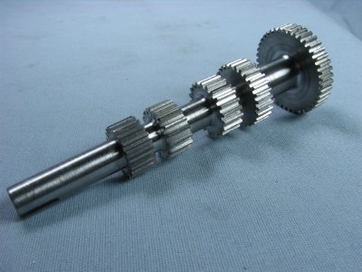
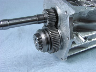
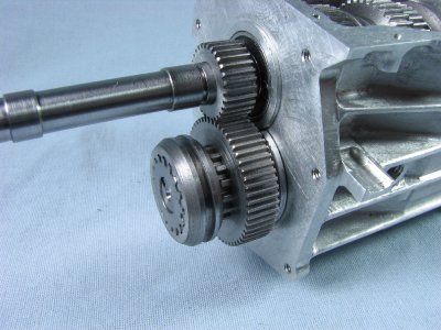
One of the issues that needed to be addressed was the type of gears in the box. Most all modern day transmissions have helical gears in them mainly because they run smoother which equates to quieter operation. A fellow on another forum had come up with a way to make helicals in the home shop but that would have required making tapered sleeves for each each gear to get the right helix. I really didn't want to go to that extreme so I settled on spur gears. Even at that I had to solve some problems. As the trans would be a direct 1/3 copy I wanted to keep the scale dimensions as close as possible. With the main shaft to countershaft spacing set I started figuring out how I could make the gears that would fit that center to center dimension and still have progressively varying ratios. I ended up making 3 hobs of different pitches to cut the gears, 36, 40 and 48. Although visibly looking at the gears inside the case they look the same there are the 3 different pitches.
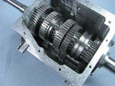
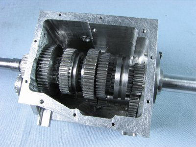
This type of transmission is commonly referred to as a constant mesh transmission. That means that all the gears are turning while the mainshaft is rotating. To select the proper gear a splined bushing is moved between gears and the splines engage with equally splined gears. There is of course synchronizers but I simplified these.
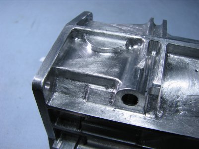
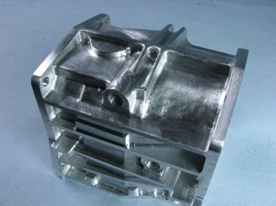
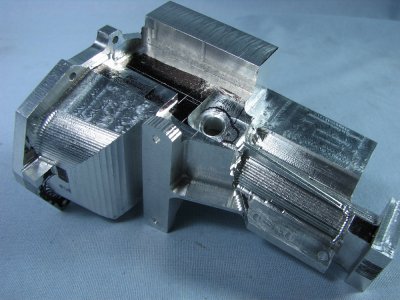
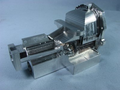
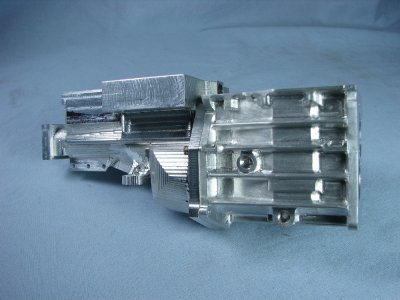
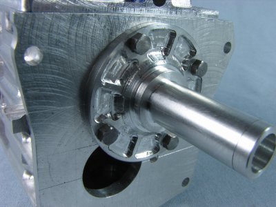
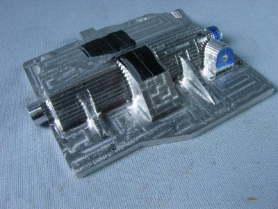
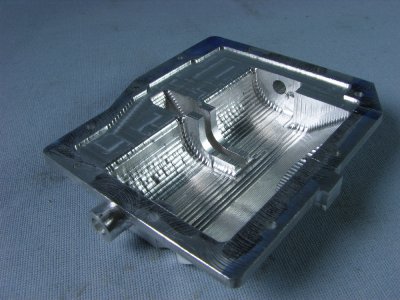
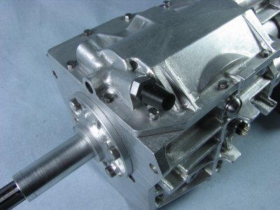
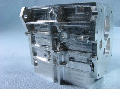
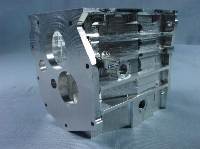
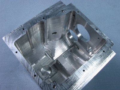
The main cases are made from 6061 aluminum. The gears are made from 12L14 steel. The shafts are W-1 drill rod and various bits are steel and bronze. The shafts ride on ball bearings at each end.
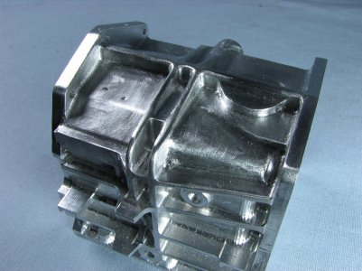
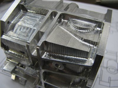
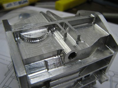
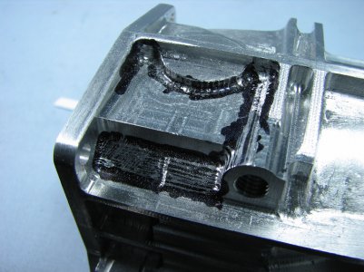
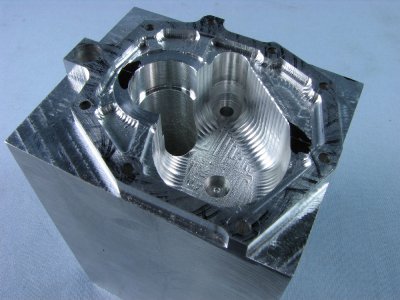
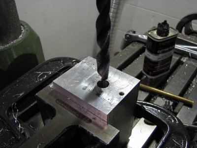
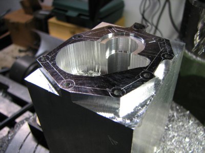
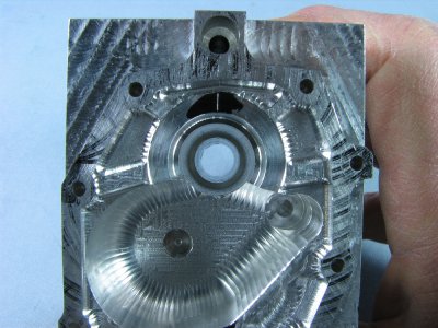
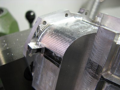
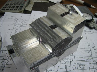
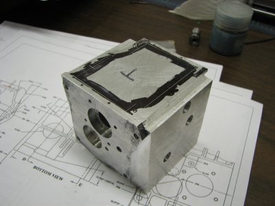
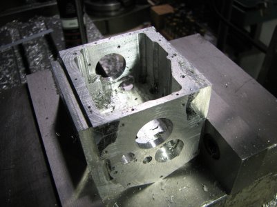
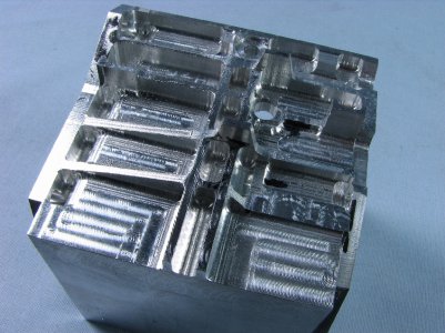
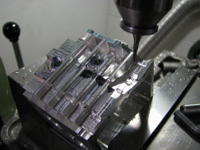
I started with a block of aluminum, layed it out, machined all the shaft and bolt holes and then started whittling away on the inside first and then the outside.
gbritnell


