- Joined
- Jun 28, 2021
- Messages
- 142
Last year Hurricane Ian came to town and did a bit of damage to my hangar including destroying the 10' x 12' roll up door on the west end of the building. When that door failed, the wind entered the building and the latches on the large east-facing door failed. That big bi-fold door stayed attached to the building and really only received minor damage -- it could have been worse. One thing that was damaged and torn off was a piece of trim from the roof area. That cap piece was 20' long and it took a couple of hours to come completely off and land on the ramp in front of the hangar. The gutter was also damaged in one spot where a pine tree fell against the south wall. The cap and the gutter profiles share some features but the gutter is the more difficult to create because it's a three-sided box shape.
After the hurricane it was either difficult or impossible to get any help with repairing damage. Everyone with any skills was busy or they were unable to get materials. I finally got material to replace the screen structure that blew out but I had to do the installation myself. The new roll-up door is on order and I expect to get on their install schedule late this month or early next month. It will be almost a full year since Ian's visit and we're in hurricane season,,,, again. Fingers crossed this gets done soon.
There's a steel building supply company here that would normally be the perfect place to get the proprietary parts I need duplicated. Problem is they are busy making roof kits for buildings much more heavily damaged than mine. Their go-to guy for odd-ball sheet metal profiles is equally busy. But at least I could buy material from them. And I have an 8' brake so that 20' long cap piece could be made right here in my hangar in three sections. Of course I get to climb up on the roof and install them but first I need to make the cap and also figure out how to make the gutter profile on that same brake.
Below I describe how I made both profiles, concentrating on the gutter since it's the one that is the biggest challenge. This was lifted from a PM I have with Tony (C-Bag). At this point the cap sections are finished and installed. All those trim parts on the roof are now screwed down properly -- something you could not say before the storm. I need to take some of the damaged gutter parts down to confirm I have that profile correct and that will happen after rainy season is over. I did get the prototype gutter profile made so I know I can make the actual parts when the time comes.
Gutters;
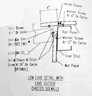
The drawing above shows the box gutter and how it attaches to the building. That and the other trim on the hangar are proprietary to the USA steel buildings. That company went under about eight years ago so there are no replacement parts available. There is a local company where people go to get custom trim parts made. They took one look at what I needed and declined to quote the job. They are super busy anyway due to the number of steel buildings needing new roofs after Hurricane Ian. They did sell me the material to roll my own.... Finding a way to mark the bends took me a while to figure out.
I modeled the cap and gutter parts in Solidworks as sheet metal parts. That means you can apply bends to the sheet metal and change the order in which those bends happen. I quickly realized the gutter would need a special bend sequence. Here's what I came up with;

The marking tool is just a piece of the galvalume that is used to mark a distance from one feature (edge, bend or bends) to another. I used a fine tip Sharpie to make the marks. In the case above the tool references from the edge of the blank to do the first 45° bend. And yes, and marking or bending errors are additive.

This bend picks up the first bend as its reference.

After the first two 45's are bent, this tool marks the next two 45° bends.

This time I go back and bend the 90° angle at the starting edge. If I had done this bend first those 45's would have been a problem due to their proximity to that edge.

Now I can do the second 90° bend.

This is where I needed to skip a bend and do the three features on the other end of the blank. This is another 45° bend.

This one is referenced off of the last one. You may have noticed the marking tools are color coded -- bronze side up tools mark the bronze side of the part, white side up marks the white side of the part. Helps keep the bends from being done backwards.

This is the second edge bend. All three of these bends fit under the brake -- barely. There's a series of plates welded together to create the upper part of the brake and the edge of one of those plates is exactly 5" back from the bending edge of the brake. That 5" dimension matches the distance of the final bend (#10) from the edge bend I did as bend#9. So just as you get your mark lined up for bend#10 the 90° flange pops behind brake's structural feature and you can no longer get to your mark. What fun....

Bend #10's tool references bend#6 to give me a 6" wide bottom and a 5" high back side.
I made some double-wall angles that slip over the edge where bend#9's edge is located that prevent that edge from slipping behind the brake's structural plate. These allow me to get the part into position for the last bend without conflicts. I made six of them and they will get spaced along that edge on the 8' long part when it's time for that last bend.

This slips over the edge and stays put during the bending but it is easy to remove afterwards. I made these by loosely forming the hem slightly off center of the blank so the edges would have a little offset. Those edges have some lead-in angle applied to the blank's long edges. I slipped a piece of .025" aluminum between the the two legs before doing the 90° bend so the bending wouldn't close up the hem feature. I had to tap the aluminum out after each bend but it came out fairly easily. I flattened out the aluminum and used that same piece to form all six double-wall angles.

This sample part was just the last four bends. It led me to believe I didn't need to address the potential conflict with the brake's structure. When I did the prototype gutter I found out that last bend was going to be a problem.

I had thought to use a spacer board and confidently wrote on this test piece "NO SPACER NEEDED" WRONG! But I came up with a more practical solution...

This is PROTO#1 of the gutter. Note I started with a too narrow flange which made the flange on the other side too wide. Other than that the part was no problem to form. You can see the thin marks from the Sharpie in this photo.

These are the actual marking tools for the various bends. Some are shared with the cap profile, some are specific to the gutter. I labeled and indicated the edge to mark on the side that was to be 'up' during the marking. The color should match the color of the material to insure you weren't about to make scrap.

The prototype parts, so far. The cap is the simpler part to create.

Old and new. The old part fits very close to the new part when you push them together. The cap parts I made are now installed and all of the caps are screwed down much better than they were originally. I don't expect a repeat of this problem in the future but I'm also hoping they don't get another test like Hurricane Ian.....
After the hurricane it was either difficult or impossible to get any help with repairing damage. Everyone with any skills was busy or they were unable to get materials. I finally got material to replace the screen structure that blew out but I had to do the installation myself. The new roll-up door is on order and I expect to get on their install schedule late this month or early next month. It will be almost a full year since Ian's visit and we're in hurricane season,,,, again. Fingers crossed this gets done soon.
There's a steel building supply company here that would normally be the perfect place to get the proprietary parts I need duplicated. Problem is they are busy making roof kits for buildings much more heavily damaged than mine. Their go-to guy for odd-ball sheet metal profiles is equally busy. But at least I could buy material from them. And I have an 8' brake so that 20' long cap piece could be made right here in my hangar in three sections. Of course I get to climb up on the roof and install them but first I need to make the cap and also figure out how to make the gutter profile on that same brake.
Below I describe how I made both profiles, concentrating on the gutter since it's the one that is the biggest challenge. This was lifted from a PM I have with Tony (C-Bag). At this point the cap sections are finished and installed. All those trim parts on the roof are now screwed down properly -- something you could not say before the storm. I need to take some of the damaged gutter parts down to confirm I have that profile correct and that will happen after rainy season is over. I did get the prototype gutter profile made so I know I can make the actual parts when the time comes.
Gutters;

The drawing above shows the box gutter and how it attaches to the building. That and the other trim on the hangar are proprietary to the USA steel buildings. That company went under about eight years ago so there are no replacement parts available. There is a local company where people go to get custom trim parts made. They took one look at what I needed and declined to quote the job. They are super busy anyway due to the number of steel buildings needing new roofs after Hurricane Ian. They did sell me the material to roll my own.... Finding a way to mark the bends took me a while to figure out.
I modeled the cap and gutter parts in Solidworks as sheet metal parts. That means you can apply bends to the sheet metal and change the order in which those bends happen. I quickly realized the gutter would need a special bend sequence. Here's what I came up with;
The marking tool is just a piece of the galvalume that is used to mark a distance from one feature (edge, bend or bends) to another. I used a fine tip Sharpie to make the marks. In the case above the tool references from the edge of the blank to do the first 45° bend. And yes, and marking or bending errors are additive.
This bend picks up the first bend as its reference.
After the first two 45's are bent, this tool marks the next two 45° bends.
This time I go back and bend the 90° angle at the starting edge. If I had done this bend first those 45's would have been a problem due to their proximity to that edge.
Now I can do the second 90° bend.
This is where I needed to skip a bend and do the three features on the other end of the blank. This is another 45° bend.
This one is referenced off of the last one. You may have noticed the marking tools are color coded -- bronze side up tools mark the bronze side of the part, white side up marks the white side of the part. Helps keep the bends from being done backwards.
This is the second edge bend. All three of these bends fit under the brake -- barely. There's a series of plates welded together to create the upper part of the brake and the edge of one of those plates is exactly 5" back from the bending edge of the brake. That 5" dimension matches the distance of the final bend (#10) from the edge bend I did as bend#9. So just as you get your mark lined up for bend#10 the 90° flange pops behind brake's structural feature and you can no longer get to your mark. What fun....
Bend #10's tool references bend#6 to give me a 6" wide bottom and a 5" high back side.
I made some double-wall angles that slip over the edge where bend#9's edge is located that prevent that edge from slipping behind the brake's structural plate. These allow me to get the part into position for the last bend without conflicts. I made six of them and they will get spaced along that edge on the 8' long part when it's time for that last bend.
This slips over the edge and stays put during the bending but it is easy to remove afterwards. I made these by loosely forming the hem slightly off center of the blank so the edges would have a little offset. Those edges have some lead-in angle applied to the blank's long edges. I slipped a piece of .025" aluminum between the the two legs before doing the 90° bend so the bending wouldn't close up the hem feature. I had to tap the aluminum out after each bend but it came out fairly easily. I flattened out the aluminum and used that same piece to form all six double-wall angles.
This sample part was just the last four bends. It led me to believe I didn't need to address the potential conflict with the brake's structure. When I did the prototype gutter I found out that last bend was going to be a problem.
I had thought to use a spacer board and confidently wrote on this test piece "NO SPACER NEEDED" WRONG! But I came up with a more practical solution...
This is PROTO#1 of the gutter. Note I started with a too narrow flange which made the flange on the other side too wide. Other than that the part was no problem to form. You can see the thin marks from the Sharpie in this photo.
These are the actual marking tools for the various bends. Some are shared with the cap profile, some are specific to the gutter. I labeled and indicated the edge to mark on the side that was to be 'up' during the marking. The color should match the color of the material to insure you weren't about to make scrap.
The prototype parts, so far. The cap is the simpler part to create.
Old and new. The old part fits very close to the new part when you push them together. The cap parts I made are now installed and all of the caps are screwed down much better than they were originally. I don't expect a repeat of this problem in the future but I'm also hoping they don't get another test like Hurricane Ian.....
Last edited:


