Budget VFD with external braking resistor support

FliesLikeABrick

Wastestream salvage addict
H-M Lifetime Diamond Member
Joined
Oct 30, 2019
Messages
197
Hi team,

I purchased a cheap $90 KCLY "2HP" VFD off eBay last year for my new drill press. It is amazing what $100 gets you in terms of configuration (and documentation) for industrial lego pieces on a budget!

The manual indicated that the unit had terminals and configuration for external power dissipation, as well as some internal capacity when external resistors are not available.

In the months I have owned it, the internal braking does largely meet my needs -- but in certain situations I can trip it, unless I adjust many settings to be very conservative.

So, I removed the plastic knockouts covering the PB+ and PB- terminals, and wired in the correct resistors mounted on an aluminum heatsink. However, no combination of settings results in the external resistors being used. I have reached the conclusion that this $90 product, unsurpririsingly, doesn't have the extra bits to support external power braking.

--
That all said, I need a VFD for another project, and can move this one to it. This leaves me looking for a VFD that supports external power braking resistors, so I can put it on the larger drill press. I'd love if it could use the existing resistors I have mounted, 100 ohm (two 200ohm in parallel), good for up to 100W of dissipation, which I can of course reconfigure to 50ohm or 200ohm ohr 400ohm if needed to suit a particular VFD

Any suggestions for budget VFDs that actually work with external power resistors? I do not mind cheaper import devices, after being impressed with what is available - of course I will take the ratings at face value and over-size the unit...

Thanks all - I just don't trust my eBay browsing to turn up results that actually will use the external resistors, after being burned last time. I am of course not complaining - you get what you pay for...
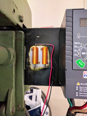
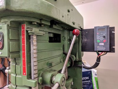
IMG_20201109_135433.jpg

IMG_20201029_112942.jpg
 
Last edited:
I can help you out here. Will post some ideas.

As an industrial controls guy, your braking resistor setup scares me a bit. Assuming your VFD is running off of 240VAC, those braking wires will be carrying ~325VDC which is dangerous from a shock hazard. Also if they were to short to the metal strip the resistors are mounted to, the VFD would probably be fried from the overcurrent. Let's get you a properly made VFD braking resistor with high temperature insulated leads.
Thank you for your input - I appreciate your concern for these failure modes. These resistors are so far a proof-of-concept, I to intend to add extra insulation and human protection to it, but was trying to prove that the VFD had external braking capacity before going down that path. Hopefully I can put your mind at ease a bit while we discuss VFD options, with a few notes:
  • The metal mounting plate has its own dedicated ground run to the upstream contactor's junction box and tied into the incoming ground from the power supply
  • I will be pop-riveting insulating fiber board behind the exposed electrical connections, to reduce the chances of an impact pushing the exposed contacts against the backplate
  • I have a cover that will mount over this entire setup, similar to the perforated cages around commercial products
  • This whole setup can be unscrewed and re-mounted to the backside of the plate, away from the operator
  • The conductors are 90C-rated, and can additionally be sleeved with fiberglass (including between the resistors, with a bit of un-and-re-soldering) to prevent chafing or reduce the probability of contact in the case they were otherwise damaged.

That all said, I am not above replacing this with a commercial solution, once I know I have a VFD that can properly use the additional investment.
 
AutomationDirect is my source for low cost *good* automation components. No guesswork with Amazon or Ebay, real manuals, real support.

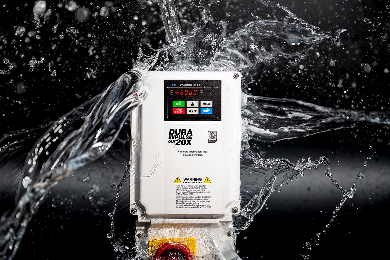
For a basic VFD, I'd recommend the GS20 series VFDs. The 2HP model (230V 1P) is GS21-22P0 ($188) and has an option for an external 200W braking resistor GS-BR-200W091 ($30). The drive has Sensorless Space Vector Control (SVC) and Sensorless Field Oriented Control (FOC) which gives much better low speed torque in the motor compared to a basic V/Hz drive from eBay. It also has Safe Torque Off (STO) inputs which are a true safety rated method to ensure the motor has no power when an ESTOP is hit.


This particular VFD does not appear to have an internal resistor for dynamic braking. The external resistor is rated for braking at 125% of motor max rated torque, which will stop the motor FAST.
 
Last edited:
Also, with a trusted supplier, I see no reason to arbitrarily oversize a VFD. See the duty rating tables in the manual to understand the overload ratings. These are usually under the CT/VT (Continuous/Variable Torque) section in the manual.
 
Also, with a trusted supplier, I see no reason to arbitrarily oversize a VFD. See the duty rating tables in the manual to understand the overload ratings. These are usually under the CT/VT (Continuous/Variable Torque) section in the manual.
100% agreed, the oversizing was arbitrary and based on being skeptical of the cheap eBay options. I will look at your recommendation and comment back here if I have any questions or end up placing an order. This pricing is much more reasonable than I expected as well, thank you!

As for E-Stop - thanks, I was trying to figure out the best way to implement emergency stop, and this sounds like a good balance (via the VFD, but not just a normal "stop" command; and not just cutting power to the VFD from upstream)
 
Yup! AutomationDirect is a great middle ground of cheap enough to be reasonable + good free phone support, manuals, and quality products. They are my go-to for all home projects.

Safe Torque Off is an industry standard and each product is qualified by a standards agency.


This would 100% be my method to implement ESTOP control on the machine.
 
Order placed - thank you for the quick reply and great information.
 
I recently bought a G20 to get my mill running. I have a couple questions, for which I’m happy to start a new thread but are prompted by the discussion above.

1. For an e-stop, there appear to be a couple options. One is the STO inputs, which kills motor drive power and coasts to a stop. The other is setting a digital input to a value of 10 (external fault, EF) or 28 (emergency stop, EF1). EF may be configured to decelerate; EF1 is coast to stop. Using EF to stop ASAP seems beneficial to me in many circumstances but I’d like to better understand the trade offs. Seems like STO is the highest-reliability approach to killing power.

2. When would one choose Sensorless Vector (SVC) versus Field-Oriented Control (FOC)? It sounds like FOC is generally better, but with an older motor as I have (2-speed 2-hp from 1980), does that mean I should not be using FOC, or does it just limit my frequency range?
Safe Torque Off is the right way to do this. The reason is that the function is executed in specially designed hardware with an extremely low probably of dangerous failure (i.e. the motor does not stop when the ESTOP is hit). The function also allows you to wire dual channels into the function. This help limit risk of shorted or broken wiring leading to a dangerous condition where the ESTOP does not function as required. IF you use a digital input, you are trusting software to take care of the function for you, and you do not get the drive's safety rating.

SVC and FOC are both higher performance motor control algorithms which help reduce motor heating and provided a wider speed band (how slow you can go before the VFD can no longer provide the motor rated torque). V/Hz is typically between 5:1 - 10:1, SVC can be 100:1 (GS20 drive w/o encoder offers 50:1), and FOC is 1000:1 or better (GS20 drive w/o encoder offers 100:1). You typically need to add an encoder to the motor to get the maximum speed band. These control methods should be applicable to all motors provided you know the motor data. SVC and FOC require knowledge of more motor nameplate data than V/Hz for most drives.
 
Last edited:
Back
Top