Building a steady rest

Today I finish machined the steady rest body. I fly cut .010" off the three flat surfaces where the arm assemblies go, then I chucked up the body and skimmed .008" off each side using a HHS tool with a .030 radius on the point. this gave me a very very smooth and shiny surface. I was going to paint the steady rest body, but it came out so nice , I am going to leave it natural I believe. I installed the first telescoping assembly and it took about three hours. The next two will go much quicker. My worst fear did cause a little bit of trouble and that was the threads are cut at about a class 3 fit. They fit tight and smooth individually , but when I assemble the right hand and left hand threads into the same assembly to work together, I may wish I had cut a class 2 thread. Sure enough after installing the assembly It worked great until I pinned the knob to the screw. This removed any ability for the assembly to "move" a little and the threads got a little tight. After working it a few times and oiling the threads the installed assembly works by hand. It is a little bit stiff over the whole range of travel , but is OK to turn by hand. A little stiffness is probably good because vibration will not move it. South bend put a brass pin held with a wire spring ring on the knob to give it a little drag when turning to keep it from moving from vibration. I chose not to include this on my version and it isn't needed anyway because the stiffness is kind of built in my unit. Over all, I am very pleased with the way this is turning out. I won't bore you with the installation of the other two arms , which I will do tomorrow, but will post an update on the finishing up of this project with some photos.

Mark
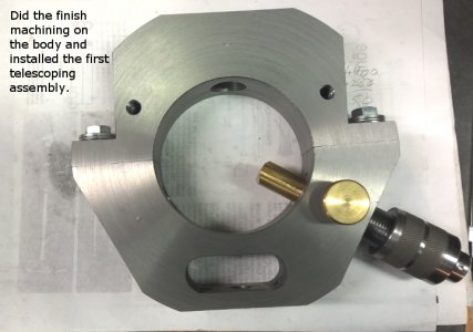
finish machined steady rest.jpg

finish machined steady rest.jpg
 
Well boy and girls.... THE STEADY REST IS FINISHED. I installed the other two arms and polished up a few parts and it fits the lathe perfectly. This was a long build and I will agree, a challenging one. the close tolerances made it the most difficult. the arms move freely. I can turn the adjustment knobs with two fingers. there is just the right amount of drag to keep vibration form causing any problem and the locks hold the arms solid.

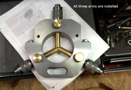
steady rest 24.jpgI got all three arms installed
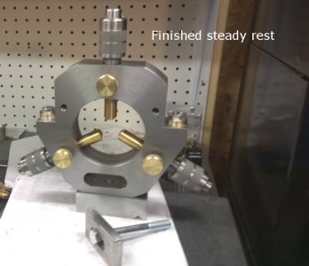
steady rest 22.jpgThis is the completed steady rest
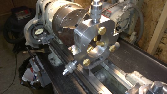
steady rest 21.jpgHere it is on my lathe
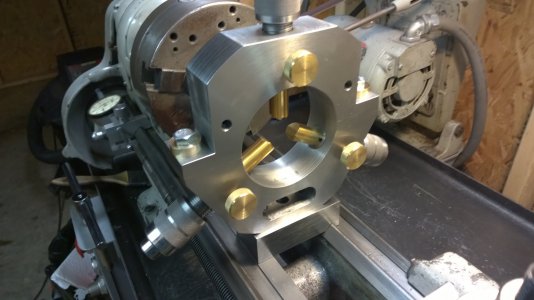
steady rest 20.jpgNotice , I made a couple heavy duty brass washers to go under the bolts holding the steady rest halves together. I am going to replace the bolts with stainless steel cap screws for looks.

Thanks to all who followed this project,

Mark


My next big project is going to be the Bonelle tool and cutter grinder. I will be building other items also. Right now I am gathering material for the Bonelle

steady rest 24.jpg steady rest 22.jpg steady rest 21.jpg steady rest 20.jpg
 
Great looking project Mark. You did a good job with the finish work and it looks like a lot of thought was put into each part and procedure. It looks substantial enough to machine well drilling shafts with confidence.

Rick
 
Mark
Is there any chance of getting the drawings for the telescoping assemblies? I love how it all come together. I was thinking the maybe if you polish the threads that they might move more freely.
Enjoyed
Nelson Collar
 
Mark
Is there any chance of getting the drawings for the telescoping assemblies? I love how it all come together. I was thinking the maybe if you polish the threads that they might move more freely.
Enjoyed
Nelson Collar

Yes I can give you drawings. There are changes in the dimensions from the S.B. drawings because I had to change the left hand threads to 3/8-16 instead of the 3/8-10 that S.B. used. this meant the sleeves fingers and even the knobs are longer to get enough travel and stay engaged. My prints will have the new dimensions on them.
I was amazed my assemblies work pretty darn smooth and have just enough drag that I don't need to incorporate the spring and pin S.B. used to keep the knobs a little stiff. I can turn them easily with my thumb and finger. You want a close fit on the threads , that is why I did most of them with a 4 jaw because a couple thou runout will cause problems when assembled. keeping everything concentric is important in this assembly.
PM me and I will forward you my drawings. it may take a day or two. I got a new printer and am in the process of putting all my project prints on my website. If you plan on building one of these steadys I can give you more photos and hints I worked out in the process. it would be an easy build now that I know how to do it. The difficult part was having to remake some parts because of things I hadn't thought of that caused some difficulty and figuring out how much to change the dimensions.

Mark
 
Mark
I understand what it is like when not having drawings of something someone already built. I have always liked the telescoping adjustment. I figured one had a clock wise thread and the other was counter clock. It is just easier, I plan to pour my steady rest either in brass or aluminum. Haven't made up my mind.
Thank
Nelson Collar
 
Nelson

That is why I built it. I wanted the telescoping adjustment at a price I could afford. I carved my steady rest body out of a 7 1/4" steel round 1 5/8" thick. really filled up the 9 inch lathe

Mark
 
Nelson,

All my prints for almost all my projects including the steady rest are on my web site

mark
 
Nice job and god pictures.
Im thinking of to build a follow rest the same way.

So I hope I can use some of the same princips?
 
Could you please direct to your web page?

"Billy G"
 
Back
Top