Calling All Electronics Geniuses !

Hi Brooks,

I'm one of them electronics guys..............but I'm no genius!

For me only one thing taught me how these rocker switches are wired and that was taking one apart to see how it works. Now that I know how they work, I can even picture in my mind which pins are connected when it's in a particular position.

I am _NOT_ suggesting you do that with yours, but I've done it enough times(*-see below) I popped one apart to take some pictures.

Here's all the parts in mine laid out in a row:
parts2.jpg

The two little silver bits (second from the right) above are the metal contacts. These things simply teeter-totter within the switch body (far right). They pivot on the middle pins (1 and 2 in your case), and connect them to either corner pin. Here's a shot looking inside the body:
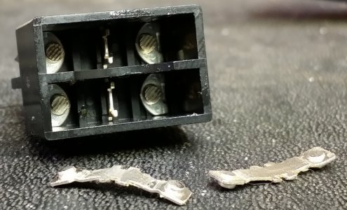
contacts2.jpg

the middle pin 1 connect to either 1A or 1B.
the middle pin 2 connects to either 2A or 2B.
the two haves are ganged together, such that when pin 1 connect to 1A, then 2 connects to 2A.
no pin on the "1" side every connects to a pin on the "2" side.

I guess I'm a visual learner and this I could actually see; unlike those friggin' tiny electrons they tell me whiz about in the wires......

-brino

(*) at work they use some decent metal power bars, with a good long and heavy input cord, a total of eight outlets, a switch, a circuit breaker and power light all in a tough aluminum housing.
However, when the switch starts misbehaving they simply put them in the garbage can. Whenever I find one in the trash it comes home with me. I have fixed 3 or 4 simply by cleaning the switch!
One other one just needed the switch replaced. I am slowly replacing all the crappy "dollar store" extension cords/power bars in my shop with these.
 
Please make sure the switch is rated at the right voltage (125 volts I assume). There are a lot of similar switches for automotive use rated at 12 volts. I accidentally hooked up one the other day and it didn't last 5 seconds.
 
Hi Brooks, i'm not a genius either but a close up of the side of the switch explained a lot for me anyway,
the switch is a double pole double throw switch that is rated for 20 amps 125v volts.(16a @ 250v you're good no worries)
you can hook up a neutral on one pole and a hot lead on the other pole and isolate the output circuit from the input circuit.
for sake of argument the, most of the time you would utilize the center lugs for input,
in other words, you'd put a hot lead(usually black in AC power) on one center terminal and the white(neutral).
when you actuate the rocker in either direction, you'll switch the incoming power to output power , possibly on both legs.
it can be wired in to be used as a reversing switch with a little planning.
i'd be happy to help out, hit me up, i'll see if i can walk you through.
 
1, 1a & 1b is one side/pole of the switch and 2,2a & 2b is the other side/pole of the switch. The contacts that are marked 1 and 2 are the center poles. The other poles are used for switching. For example; if you ran a wire to the #1 and another wire to the #1a contact, rocking the switch would turn on and off that wired circuit…Good Luck, Dave.
 
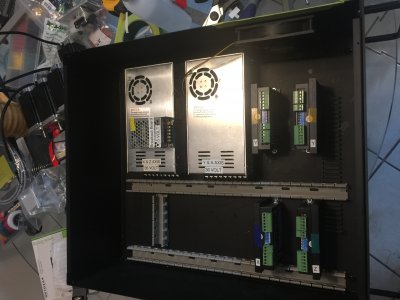
Thank you everyone! I did not have to eat to much paste your guys are so fast on the reply. I could have taken my meter and checked, but I am not that skilled with electronics, and not confident in my conclusions so I asked you all to help out. This is the beginning of a control box for a CNC router my son and I are building. I am confident when I have a wiring diagram to follow, as I have been reading plans my whole life. I run into questions when I have to finger stuff out myself, not so easy. Here is a picture of the box so far.IMG_0372.JPG
 
Hi Brooks, i'm not a genius either but a close up of the side of the switch explained a lot for me anyway,
the switch is a double pole double throw switch that is rated for 20 amps 125v volts.(16a @ 250v you're good no worries)
you can hook up a neutral on one pole and a hot lead on the other pole and isolate the output circuit from the input circuit.
for sake of argument the, most of the time you would utilize the center lugs for input,
in other words, you'd put a hot lead(usually black in AC power) on one center terminal and the white(neutral).
when you actuate the rocker in either direction, you'll switch the incoming power to output power , possibly on both legs.
it can be wired in to be used as a reversing switch with a little planning.
i'd be happy to help out, hit me up, i'll see if i can walk you through.

Thanks Mike, I actually do have a question for you. What would the best way to wire up LED status lights for each axis and the break out board. I am assuming a relay would be required for each voltage, 36 volts and 5 volts, I am just not sure what to buy and how to wire it. I just want to be able to confirm power to each axis and the break out board. It will also look pretty cool with a bunch of lights on the front panel, LOL I could get really fancy and wire a readout for the voltage of each power supply, but that would probably be overkill. This whole box along with the VFD will be mounted in a slide out rack under the table, so lights would be a quick way to confirm that all is well.
 
you have lotsa room to play!!!!:D
if you can post the diagram somehow that'd be great-others can help a little easier with the info, if necessary
 
Thanks Mike, I actually do have a question for you. What would the best way to wire up LED status lights for each axis and the break out board. I am assuming a relay would be required for each voltage, 36 volts and 5 volts, I am just not sure what to buy and how to wire it. I just want to be able to confirm power to each axis and the break out board. It will also look pretty cool with a bunch of lights on the front panel, LOL I could get really fancy and wire a readout for the voltage of each power supply, but that would probably be overkill. This whole box along with the VFD will be mounted in a slide out rack under the table, so lights would be a quick way to confirm that all is well.

the led's can easily be powered by 5v signal, because there is little consumption.
a circuit could be thunk up to take a 35v input and trigger an led that has a resistor in series to take the voltst to acceptable levels.
as far as wiring in voltage/amp gauges and the like is all possible. if you feel you'd like to know the information there is a way to display and analyze it.
were limited by your imagination and your will, friend.
 
I have a stack of diagrams about 3/4" tall. I am not sure which diagram would be most helpful. The power supplies are labeled with which part they are going to power. I am such a beginner with electronics, I am just winging this thing. I figure when I am all done I will know what not to do for sure. My plan is to wire and test each axis one at a time. That way I will have fewer variables to work with.
 
where'd you get it from???, maybe they have a pdf i could download and have a better clue...
 
Back
Top