Can I Reverse This 1ph 230V Taiwanese Motor

rdhem2

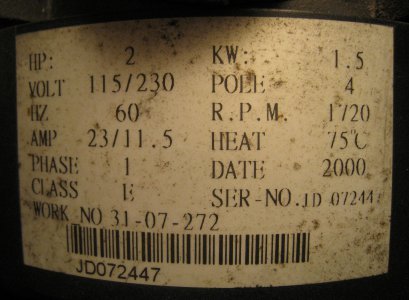
Here is the data you asked for in pictures (worth a thousand words).
IMG_5499.jpgIMG_6715.jpgIMG_6717.jpgIMG_6737.jpgIMG_6739.jpgShop 627.jpg

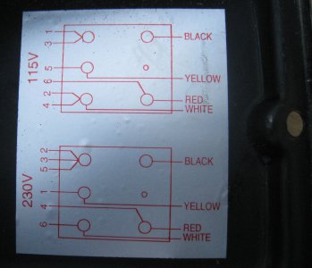
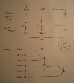
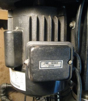
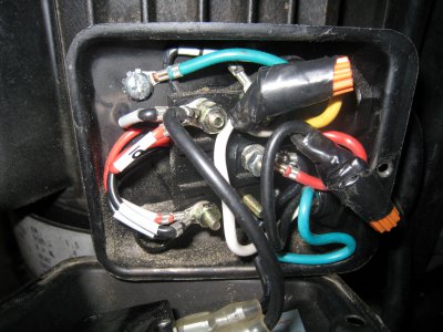
The hand diagram shows exact wire identification and colour. What I need most I guess is to confirm that switching BLK2/3 over to Red6 and switching BLK4 over to Red5 is the correct way to get REV because I have no idea what the wires are attched to inside the motor. If so, I'll work out a way and position to mount the DPDT switch. Also, are we saying that a normal 4 way house switch from HD, for instance, will do the job?.

At the moment this method appeals to me because it will allow me to keep the ON/OFF switch on the front and the current appearance of the mill.

Looking forward to your suggestions.

Thanks
Canuck75

IMG_5499.jpg IMG_6715.jpg IMG_6717.jpg IMG_6737.jpg IMG_6739.jpg Shop 627.jpg


Good Sir;
How is your reversing project going? I have held backfrom wasting your time because Ulma Dr.shot you the fix in the second reply.

A four way switch would work but would only be usable when the drill press has come to a complete stop. There is no way to instantly reverse a single phase motor that I am aware of. The motor must slow down enough to re-engage the centriugal switch in the motor its self. Keep us posted until she is running and pileing up SWARF!

- - - Updated - - -


Good Sir;
How is your reversing project going? I have held backfrom wasting your time because Ulma Dr.shot you the fix in the second reply.

A four way switch would work but would only be usable when the drill press has come to a complete stop. There is no way to instantly reverse a single phase motor that I am aware of. The motor must slow down enough to re-engage the centriugal switch in the motor its self. Keep us posted until she is running and pileing up SWARF!
 
Thanks for all the input gents, it gave me the courage to try switching the Red 5 and Red 6 wires and reverse worked without fuss.

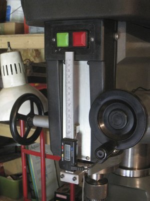
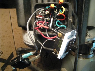
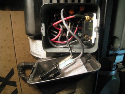
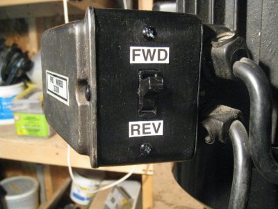
Anxious to try this mod at minimum cost, I did indeed purchase a 4 way switch from HD, and, just had to make a 2 1/2" extender for the existing motor terminal box to accomodate the switch. Because there were 2 spare posts on the terminal block, I only needed to make a couple of 6" jumpers to hook it up without compromising a return to the original setup. Continued use of the original start/stop on the front keeps the look of the machine as well.

I have run it at 3000 RPM for about 15 minutes in forward and reverse with no apparent heat build up in the switch. Since the motor will always be stopped when changing direction there will be no power on the 4 way and thus no arcing of the contacts when changing direction, so thought I would give it a try. Starting it in the highest speed draws the most current (noticeable spin up time difference) and so far no smell,heat, popping of the reset breaker. If it eventually does fry I'll get a beefier switch. Here is a look at how it turned out.

IMG_6745.jpgIMG_6746.jpgIMG_6748.jpg


The reason I wanted to do this stemmed from using the boring head on large diameter holes where I needed to stick a short boring bar out the side of the of my 2" boring head. The way the carbide tips are brazed on these bars the normal rotation would have to be CCW, or, bore from the bottom up. Regrinding an existing bar tip to bore CW with down feed would not leave much of a tip so didn't consider this. A reverse capability means I don't have to get different boring bars. Now the true test will be if the switch stands up over time. We'll see. This was so much easier than trying to wire in a drum switch.

So, once again thanks to everyone for their input. Would still like to hear any further advice or comments. I've got a thick enough skin so lets hear it.

Cheers
Canuck75

IMG_6745.jpg IMG_6746.jpg IMG_6748.jpg
 
Thanks for all the input gents, it gave me the courage to try switching the Red 5 and Red 6 wires and reverse worked without fuss.

Anxious to try this mod at minimum cost, I did indeed purchase a 4 way switch from HD, and, just had to make a 2 1/2" extender for the existing motor terminal box to accomodate the switch. Because there were 2 spare posts on the terminal block, I only needed to make a couple of 6" jumpers to hook it up without compromising a return to the original setup. Continued use of the original start/stop on the front keeps the look of the machine as well.

I have run it at 3000 RPM for about 15 minutes in forward and reverse with no apparent heat build up in the switch. Since the motor will always be stopped when changing direction there will be no power on the 4 way and thus no arcing of the contacts when changing direction, so thought I would give it a try. Starting it in the highest speed draws the most current (noticeable spin up time difference) and so far no smell,heat, popping of the reset breaker. If it eventually does fry I'll get a beefier switch.

Congratulations! Sounds like you did all the right things, and gave it a pretty thorough test as well. I think your switch will probably hold up nicely. IIRC, they're rated for something like 15 amps, and a 2HP motor (at least mine) draws around 8.

I especially like your "Continued use of the original start/stop on the front keeps the look of the machine as well." I've always tried to preserve the appearance and function of the original controls when making mods. Nice extension on the motor terminal box!
 
Mr. Canuck75:

Very nice job on fitting that big old four way in the motor peckerhead. Would never have thought you could make it fit!

Your switch is fine. Because it is in the starting circuit, it only carries current until the motor comes up to speed and the starting switch opens.

Again,nice solution!!!!!!!!!!!!!
 
Have been out of town so just got to see the last few comments. Thanks for your views. I will certainly let you know if normal ops cooks the 4-way.

However, I would still like to get an answer to the question that when using a drum switch, there is still one hot lead from the 220V line (115V potential) on the motor when the switch is in the OFF position. All the wiring diagrams thus far show this same quirk!

Does this not matter? Personally I would prefer that no power is on the motor whatsoever when in the OFF position.

Anybody??


Canuck75
 
Have been out of town so just got to see the last few comments. Thanks for your views. I will certainly let you know if normal ops cooks the 4-way.

However, I would still like to get an answer to the question that when using a drum switch, there is still one hot lead from the 220V line (115V potential) on the motor when the switch is in the OFF position. All the wiring diagrams thus far show this same quirk!

Does this not matter? Personally I would prefer that no power is on the motor whatsoever when in the OFF position.

Anybody??

Canuck75

Look back at post #5 in this thread. My second wiring diagram shows how to do it.

- John Herrmann
 
Thanks very much John, I'll apply my noggin to your second diagram once again to see if I want to switch over now that I have set it up with the 4-way. To start with I would need to assure myself that the numbered leads on my motor are properly identified to match up to your schematic.

You have said that a hot lead on the motor also gives you the willies, but based on what I have read on this forum, there must be a lot of motors out there wired up this way, so why no alarm bells?


Canuck75
 
You have said that a hot lead on the motor also gives you the willies, but based on what I have read on this forum, there must be a lot of motors out there wired up this way, so why no alarm bells?

Canuck75

My best guess is that others do what I originally did ... add a service disconnect nearby, or else plan to unplug the tool when servicing the motor.
 
Back
Top